Vestil WL-100-5-68 Bruksanvisning
Vestil
Ikke kategorisert
WL-100-5-68
Les nedenfor 📖 manual på norsk for Vestil WL-100-5-68 (16 sider) i kategorien Ikke kategorisert. Denne guiden var nyttig for 16 personer og ble vurdert med 5.0 stjerner i gjennomsnitt av 8.5 brukere
Side 1/16
6/25/2015 Manual, WL-100.doc
OPERATION &
M
AINTENANCE
M
ANUAL
VESTIL MANUFACTURING CORP.
2999 N. Wayne St., Angola, IN 46703
Ph: 260-665-7586 · Fax: 260-665-1339
E-mail: sales@vestil.com
· www.vestil.com
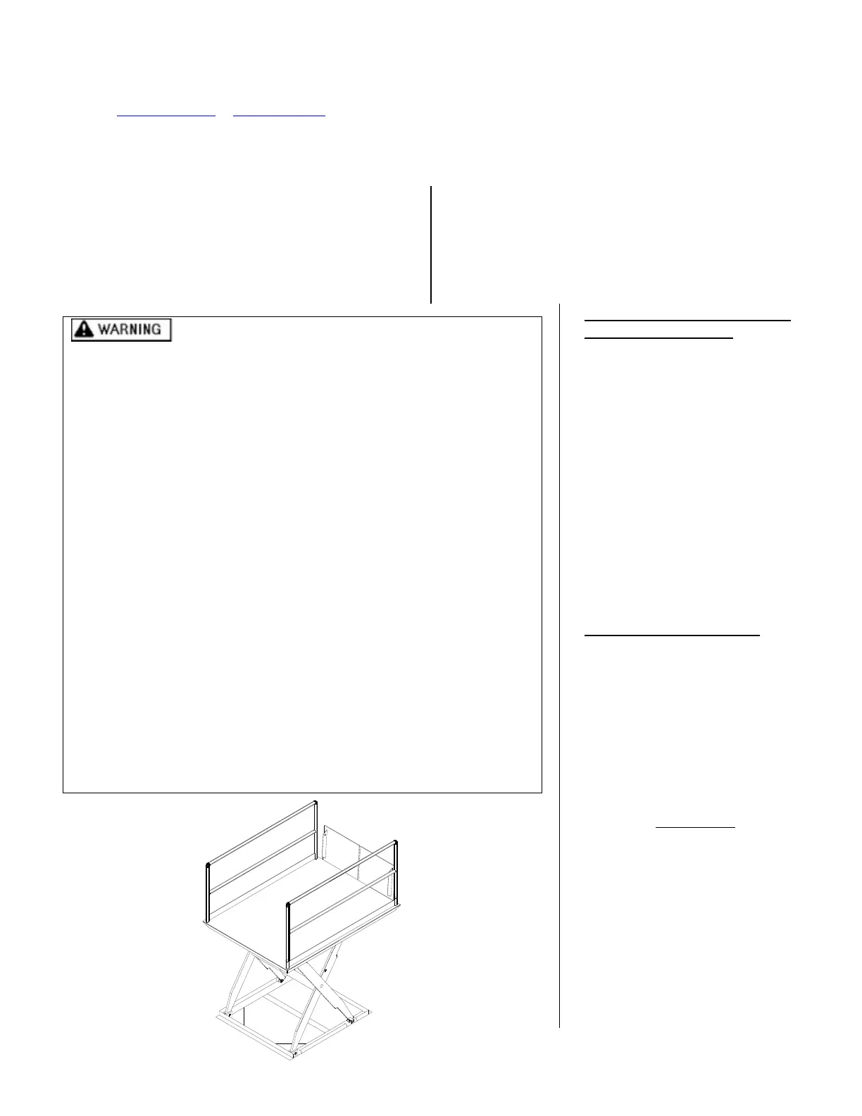
MODEL WL-100
Pre-installation Instructions ............................................ 2
Installation Instructions ................................................... 3
Routine Maintenance & Safety Checks .......................... 4
Operation Instructions ..................................................... 5
Structural Expl View & BOM ....................................... 6
Power Unit’s Operation .................................................. 7
Motor & Transformer Connections ................................ 8
Electrical Diagrams ..................................................... 9-10
Power Unit Expl Parts Drawing & BOM .................... 11
Manifold Expl View & BOM, Hydraulic Diagram ..... 12
Power Unit Expl View & BOM .................................. 13
Troubleshooting …………………………....….……. 14
Safety Label Identification .......................................... 15
Warranty ………………………………….….……… 16
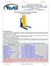
Material handling is inherently dangerous. To reduce
the likelihood of operator and bystander injury:
o Each person who might operate, use, or maintain this device must
Read and understand this manual in its entirety before operating,
using or performing maintenance on the scissor dock.
o DO NOT work on this device unless it is fully lowered and unloaded
and maintenance props are in place.
o Ensure that all safety and warning labels stay in place and are
legible. See the labels page in this manual.
o The scissor dock’s frame must be securely anchored in concrete.
See the installation instructions.
o Do not use the lift if any damage or unusual noise is observed.
o Always watch the platform and any load on it carefully when the lift
is in operation.
o Do not exceed a travel rate of two feet per second when moving
across the platform.
o The platform’s load ratings must be observed at all times. See the
operation instructions.
o Do no modify the lift without the express, written authorization of
Vestil. Unauthorized modifications might make the scissor lift
unsafe to use.
o DO NOT attempt to repair this scissor lift or perform maintenance on
it unless you are trained and authorized to do so.
o Do not use brake fluid or jack oils in the hydraulic system. If oil is
needed, use an anti-wear hydraulic oil with a viscosity grade of
150 SUS at 100°F, (ISO 32 cSt @ 40°C), or Dexron transmission fluid.
o Use only replacement parts either supplied or approved by the
manufacturer.
WHEN ORDERING
REPLACEMENT PARTS:
We take pride in using quality
parts on the equipment we
manufacture. We are not
responsible for equipment
problems resulting from the use
of unapproved replacement
parts.
To order replacement or
spare parts for this equipment,
contact the factory.
In any communication with
the factory please be prepared
to provide the machine’s serial
number, which is indicated on
the machine dataplate.
RECEIVING INSTRUCTIONS
Every unit is thoroughly
tested and inspected prior to
shipment. However, it is
possible that the unit could
incur damage during transit.
Inspect the unit closely when
it arrives. If you see evidence
of damage or rough handling to
either the packaging or to the
product when it is being
unloaded, immediately
make a
note of it on the Bill Of Lading!
It is important that you
remove the product’s packaging
upon its arrival to ensure that
there is no concealed damage
or to enable a timely claim with
the carrier for freight damage.
Also, verify that the product
and its specifications are as
ordered.
VESTIL MFG. CO./T&S EQPT. CO. 1 of 16
Produkspesifikasjoner
| Merke: | Vestil |
| Kategori: | Ikke kategorisert |
| Modell: | WL-100-5-68 |
Trenger du hjelp?
Hvis du trenger hjelp med Vestil WL-100-5-68 still et spørsmål nedenfor, og andre brukere vil svare deg
Ikke kategorisert Vestil Manualer
20 Oktober 2025
5 Oktober 2025
5 Oktober 2025
5 Oktober 2025
5 Oktober 2025

4 Oktober 2025

4 Oktober 2025
4 Oktober 2025
4 Oktober 2025
4 Oktober 2025
Ikke kategorisert Manualer
- Carel
- Totolink
- Whirlwind
- Cateye
- SHX
- Stairville
- Hegel
- Lanaform
- Supermicro
- Sesame Street
- SwitchBot
- Uvex
- Maxi-Cosi
- Bioogród
Nyeste Ikke kategorisert Manualer

23 Oktober 2025

23 Oktober 2025

23 Oktober 2025

23 Oktober 2025

23 Oktober 2025

23 Oktober 2025

23 Oktober 2025

23 Oktober 2025

23 Oktober 2025

23 Oktober 2025