Vimar ELVOX R884 Bruksanvisning
Vimar
Intercomsystem
ELVOX R884
Les nedenfor 📖 manual på norsk for Vimar ELVOX R884 (12 sider) i kategorien Intercomsystem. Denne guiden var nyttig for 11 personer og ble vurdert med 4.5 stjerner i gjennomsnitt av 6 brukere
Side 1/12
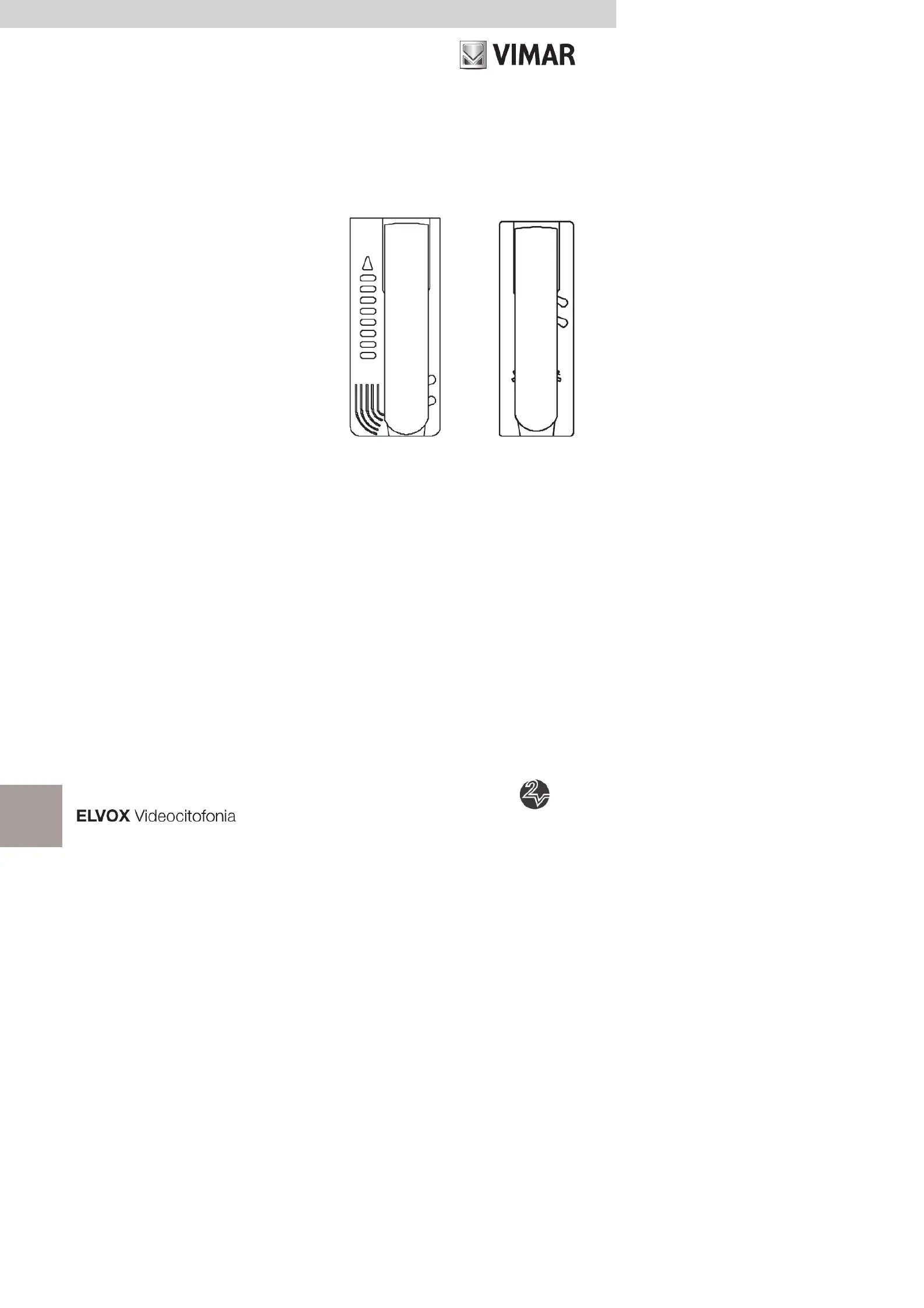
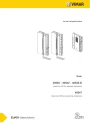
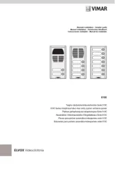
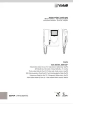
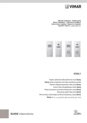
Art. 6202/A
DIGIT 2 VIDEO
Art. 887C/A
6202/A - 887C/A
Citofono per sistemi “DIGIT 2 VIDEO”
Interphones for “DIGIT 2 VIDEO” SYSTEMS
Poste d’appartement POUR SYSTEMES “DIGIT 2 VIDEO”
Türsprechanlage für “DIGIT 2 VIDEO” SYSTEME
Interfono para sistemas “DIGIT 2 VIDEO”
Telefone para sistemas “DIGIT 2 VIDEO”
Manuale installatore - Installer guide
Manuel installateur - Technisches Handbuch
Instrucciones instalador - Manual do instalador
Produkspesifikasjoner
| Merke: | Vimar |
| Kategori: | Intercomsystem |
| Modell: | ELVOX R884 |
Trenger du hjelp?
Hvis du trenger hjelp med Vimar ELVOX R884 still et spørsmål nedenfor, og andre brukere vil svare deg
Intercomsystem Vimar Manualer
25 August 2025
25 August 2025
25 August 2025
25 August 2025

25 August 2025
25 August 2025
25 August 2025
25 August 2025
25 August 2025

24 August 2025
Intercomsystem Manualer
- On-Q
- Pentatech
- M-e
- Tristar
- Toucan
- Hikvision
- Akuvox
- NuTone
- Louroe Electronics
- Somfy
- Smartwares
- Viking
- Panasonic
- DoorBird
- Mobotix
Nyeste Intercomsystem Manualer
19 Oktober 2025

18 Oktober 2025
5 Oktober 2025
4 Oktober 2025
4 Oktober 2025
4 Oktober 2025
3 Oktober 2025
3 Oktober 2025
3 Oktober 2025
3 Oktober 2025