Vollrath CBGHD-36 Bruksanvisning
Vollrath
grillplater
CBGHD-36
Les nedenfor 📖 manual på norsk for Vollrath CBGHD-36 (24 sider) i kategorien grillplater. Denne guiden var nyttig for 15 personer og ble vurdert med 3.9 stjerner i gjennomsnitt av 8 brukere
Side 1/24
Operator’s Manual
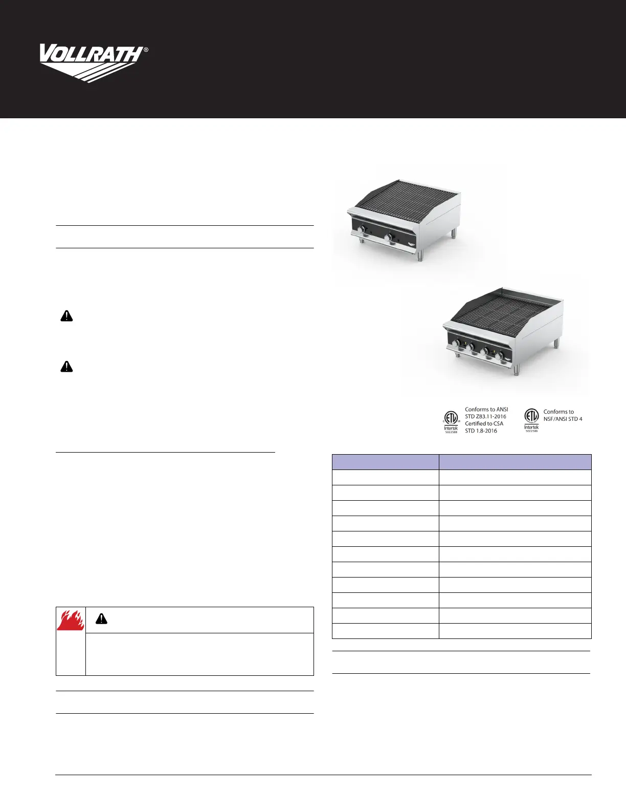
Medium-Duty and Heavy-Duty Gas Charbroilers
©
2022 The Vollrath Company L.L.C. Part No. 2350206-1 ml 2/24/22
Register your product at www.Vollrath.com/registration and become eligible to win a free 10" Vollrath Tribute
©
fry pan.
Thank you for purchasing this Vollrath equipment. Before operating the
equipment, read and familiarize yourself with the following operating
and safety instructions. SAVE THESE INSTRUCTIONS FOR FUTURE
REFERENCE. Save the original box and packaging. Use the packaging to
ship the equipment if repairs are needed.
SAFETY PRECAUTIONS
To ensure safe operation, read the following statements and understand
their meaning. This manual contains safety precautions which are
explained below. Please read carefully.
Warning is used to indicate the presence of a hazard that will or can
cause severe personal injury or death.
Caution is used to indicate the presence of a hazard that will or can
cause minor or major personal injury if the caution is ignored.
NOTICE: Notice is used to note information that is important but not
hazard-related.
To reduce risk of injury or damage to the equipment:
• Clean the equipment per the instructions in this manual.
• Do not store or use gasoline or other flammable vapors or liquids in
the vicinity of this or any other equipment.
• Keep the equipment area free and clear of combustibles.
• Do not obstruct the flow of combustion and ventilation air. The back
of the equipment must have a minimum of 6" of space.
• Use a soft cloth dampened with warm, soapy water to clean the
controls and the sides of the equipment.
NOTICE: Do not clean the griddle plate surface with soapy water.
Soapy water will corrode the griddle surface.
• Allow hot equipment cool before cleaning or moving.
• Use equipment on a flat, level position only.
• Do not operate unattended.
FUNCTION AND PURPOSE
This equipment is intended to be used for charbroiling foods in
commercial foodservice operations only. It is not intended for
household, industrial, or laboratory use.
CLEARANCE AND ENVIRONMENT REQUIREMENTS
• Must be installed adjacent to non-combustible surfaces only, with a
minimum spacing of 6" on the back of the equipment.
• Adequate clearance must be maintained to allow for proper
ventilation and servicing. 4" legs must be installed to allow airflow.
WARNING
CAUTION
WARNING
Fire, Injury, Death Hazard
Correct precautions, procedures, and regulations for usage
must be followed. Operation and safety training is necessary
for all users of this equipment.
Item/Model Number Description
CBGMD-12 Medium-Duty, Radiant, 12"
CBGMD-24 Medium-Duty, Radiant, 24"
CBGMD-36 Medium-Duty, Radiant, 36"
CBGMD-48 Medium-Duty, Radiant, 48"
CBGMD-60 Medium-Duty, Radiant, 60"
CBGHD-18 Heavy-Duty, Radiant, 18"
CBGHD-24 Heavy-Duty, Radiant, 24"
CBGHD-36 Heavy-Duty, Radiant, 36"
CBGHD-48 Heavy-Duty, Radiant, 48"
CBGHD-60 Heavy-Duty, Radiant, 60"
CBGHD-72 Heavy-Duty, Radiant, 72"
Medium Duty
Heavy Duty
Produkspesifikasjoner
| Merke: | Vollrath |
| Kategori: | grillplater |
| Modell: | CBGHD-36 |
Trenger du hjelp?
Hvis du trenger hjelp med Vollrath CBGHD-36 still et spørsmål nedenfor, og andre brukere vil svare deg
grillplater Vollrath Manualer

18 September 2025

17 September 2025

17 September 2025

24 August 2025

24 August 2025

23 August 2025

23 August 2025
23 August 2025

22 August 2025
22 August 2025
grillplater Manualer
- Globe
- Kogan
- Cadco
- Viking
- APW Wyott
- Jata
- Tefal
- Riviera Bar
- Wolf
- Krampouz
- Gorenje
- Le Marquier
- Severin
- Cuisinart
- Traeger
Nyeste grillplater Manualer

18 Oktober 2025

18 Oktober 2025
13 Oktober 2025
13 Oktober 2025
13 Oktober 2025
13 Oktober 2025
13 Oktober 2025
13 Oktober 2025
13 Oktober 2025
13 Oktober 2025