Atlona AT-AVA-EX70-2PS-KIT Bruksanvisning
Atlona
AV-forlenger
AT-AVA-EX70-2PS-KIT
Les nedenfor 📖 manual på norsk for Atlona AT-AVA-EX70-2PS-KIT (8 sider) i kategorien AV-forlenger. Denne guiden var nyttig for 44 personer og ble vurdert med 4.7 stjerner i gjennomsnitt av 22.5 brukere
Side 1/8
1
Installation Guide
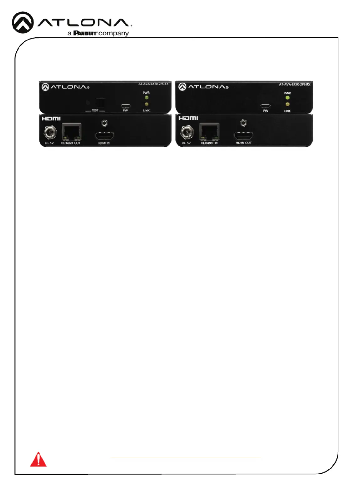
AT-AVA-EX70-2PS-KIT
4K/UHD HDMI Over HDBaseT TX/RX Kit
AT-AVA-EX70-2PS-KIT
The Atlona AT-AVA-EX70-2PS-KIT is an HDBaseT transmitter/receiver kit in the Avance™ Series,
for video up to 4K/UHD 60Hz 4:2:0 and HDMI data rates up to 10 Gbps. The AVA-EX70-2PS-KIT
is HDCP 2.2 compliant and provides HDMI transmission up to 230 feet (70 meters) for 1080p
video, and up to 130 feet (40 meters) for 4K/UHD over CAT6a/7 cable. This extender kit features
integrated HDBaseT link status testing for quick verication of twisted pair cabling integrity, as
well as HDMI clock stretching, EDID ltering, and HDMI signal regeneration for legacy HDMI
source devices. The AVA-EX70-2PS-KIT delivers a cost-eective solution for HDMI extension,
with locally powered transmitter and receiver endpoints as well as surface mounting hardware for
discreet installation.
IMPORTANT: Visit https://atlona.com/product/AT-AVA-EX70-2PS-KIT for the latest
rmware updates and Installation Guide.
1 x AT-AVA-EX70-2PS-TX
1 x AT-AVA-EX70-2PS-RX
4 x Mounting brackets
8 x Mounting screws
2 x 5V DC power supply
2 x IEC cable
1 x Installation Guide
Package Contents
Produkspesifikasjoner
| Merke: | Atlona |
| Kategori: | AV-forlenger |
| Modell: | AT-AVA-EX70-2PS-KIT |
Trenger du hjelp?
Hvis du trenger hjelp med Atlona AT-AVA-EX70-2PS-KIT still et spørsmål nedenfor, og andre brukere vil svare deg
AV-forlenger Atlona Manualer

1 Januar 2025

1 Januar 2025

1 Januar 2025

19 Oktober 2024

19 Oktober 2024

19 Oktober 2024

19 Oktober 2024

19 Oktober 2024

19 Oktober 2024

19 Oktober 2024
AV-forlenger Manualer
- Act
- Provision ISR
- DVDO
- Analog Way
- Smart-AVI
- Alfatron
- Adder
- Intelix
- Advantech
- ATen
- Crestron
- Kramer
- MuxLab
- PureLink
- Extron
Nyeste AV-forlenger Manualer

8 April 2025

2 April 2025

2 April 2025

2 April 2025

2 April 2025

1 April 2025
4 Mars 2025
4 Mars 2025
2 Mars 2025
2 Mars 2025