Avtec AXWO Bruksanvisning
Avtec
Ikke kategorisert
AXWO
Les nedenfor 📖 manual på norsk for Avtec AXWO (5 sider) i kategorien Ikke kategorisert. Denne guiden var nyttig for 13 personer og ble vurdert med 3.8 stjerner i gjennomsnitt av 7 brukere
Side 1/5
OPERATOR MANUAL
IMPORTANT INFORMATION, KEEP FOR OPERATOR
888-994-7636, fax 888-864-7636
uniedbrands.net
PART NUMBER PP MNL2207, REV. A (08/23)
This manual provides information for:
VENTILATION SYSTEMS
THIS MANUAL MUST BE RETAINED FOR FUTURE REFERENCE. READ,
UNDERSTAND AND FOLLOW THE INSTRUCTIONS AND WARNINGS CONTAINED
IN THIS MANUAL.
FOR YOUR SAFETY Do not store or use gasoline or other ammable vapors
and liquids in the vicinity of this or any other appliance.
NOTIFY CARRIER OF DAMAGE AT ONCE It is the responsibility of the
consignee to inspect the container upon receipt of same and to determine
the possibility of any damage, including concealed damage. Avtec suggests
that if you are suspicious of damage to make a notation on the delivery
receipt. It will be the responsibility of the consignee to le a claim with the
carrier. We recommend that you do so at once.
Manufacture Service/Questions 888-994-7636.
RETAIN THIS MANUAL FOR FUTURE REFERENCE
NOTICE: Due to a continuous program of product improvement, Avtec reserves the
right to make changes in design and specications without prior notice.
NOTICE: Please read the entire manual carefully before installation. If certain
recommended procedures are not followed, warranty claims will be denied.
MODEL NUMBER _________________________
SERIAL NUMBER _________________________
INSTALLATION DATE ______________________
INSTALLATION INSTRUCTIONS
Avtec hoods are provided with adjustable hanging brackets designed to receive
1/2” threaded rod with a 1/2” nut and washer. Supporting rods must be
connected to all factory installed brackets. Recommended hanging height is 6’-
6” above nished oor for canopies. Low side wall ventilators should be installed
directly upon a Avtec base or on a re rated wall. If wall mounted, the bottom of
the vent should be 36” above nished oor.
ALL AVTEC VENTILATION SYSTEMS MUST BE INSTALLED IN ACCORDANCE
WITH NFPA-96, REMOVAL OF SMOKE AND GREASE-LADEN VAPORS FROM
COMMERCIAL COOKING EQUIPMENT.
BAFFLE FILTER (AF) SERIES
Model AF ventilators are listed by UL and are built in accordance of NFPA-96
for use with UL listed re extinguishing systems for duct hood protection. They
are available with or without an automatic re damper. They utilize UL classied
removable bafe lters to extract grease and provide a limited re barrier. The
canopy contains a hidden grease trough and removable cup. Surface, plenum
and duct collar re extinguishing systems may be factory supplied.
MODULAR GREASE EXTRACTORS (AX) SERIES
Model AX ventilators are listed by UL and are built in accordance of NFPA-96 for
use with UL listed re extinguishing systems for duct hood protection. They are
available with or without an automatic re damper. These models utilize high
velocity removable grease extractors. The canopy contains a hidden grease
trough and removable cup. Surface, plenum and duct collar re extinguishing
systems may be factory supplied.
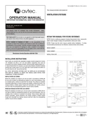
FIGURE 1
FIGURE 3 FIGURE 4
HOOD FACE
T-MOLDING
C-CHANNEL
FIGURE 2
INSULATED
SUPPLY DUCT
FIRE DAMPER &
VOLUME CONTROL
DAMPER
FLUID WEL
D
EXHAUST DUCT
ACCESS
PANEL
FRONT OR BACK
NOTE: HOLES DRILLED THROUGH HOOD ANGLE BY
INSTALLER AFTER BRACKET ATTACHMENT
POINTS HAVE BEEN DETERMINED.
HOOD
ANGLE
OF HOOD
HANGER BRACKET DETAIL
HANGER ROD
PRE-DRILLED
HOLE, ACCEPTS
UP TO 1/2"ÿ ROD
5/16" BOLT
HOLE, ACCEPTS
PRE-DRILLED
NUT
HANGER ROD
S.S. NUT & BOLT
BY OTHERS
Information contained in this document is known to be current and accurate at the time of printing/creation. Reference our product line website for the most updated
product information and specications. © 2023 Electrolux Professional, Inc. All Rights Reserved.
Produkspesifikasjoner
| Merke: | Avtec |
| Kategori: | Ikke kategorisert |
| Modell: | AXWO |
Trenger du hjelp?
Hvis du trenger hjelp med Avtec AXWO still et spørsmål nedenfor, og andre brukere vil svare deg
Ikke kategorisert Avtec Manualer
20 September 2025
11 September 2025

11 September 2025
Ikke kategorisert Manualer
- Hayward
- Cabasse
- Avantco
- Primera
- Carel
- Beemoo
- Kolcraft
- Roxio
- RF-Links
- Key Digital
- Glem Gas
- Anton/Bauer
- Ricoh
- Steiner
- Goodis
Nyeste Ikke kategorisert Manualer

23 Oktober 2025

23 Oktober 2025

23 Oktober 2025

23 Oktober 2025

23 Oktober 2025

23 Oktober 2025

23 Oktober 2025

23 Oktober 2025

23 Oktober 2025

23 Oktober 2025