Electro-Voice MB200 Bruksanvisning
Electro-Voice
høyttalerstøtte
MB200
Les nedenfor 📖 manual på norsk for Electro-Voice MB200 (4 sider) i kategorien høyttalerstøtte. Denne guiden var nyttig for 17 personer og ble vurdert med 4.4 stjerner i gjennomsnitt av 9 brukere
Side 1/4
# of Enclosures # of Kits Req’d
in Array: M
b
200 M
b
300
2 2 1
3 3 2
4 4 3
5 5 4
6 (complete circle) 6 6
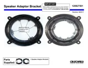
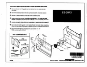
Description
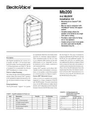
The M
b
200 installation kit consists of a
U-bracket, two M8 x 1.25 hex-head bolts,
four lock washers, two friction pads, and two
3
/
8
-24 hex-head bolts (see Chart 1). The kit
is designed to accommodate the System
200
TM
installation in a variety of ways.
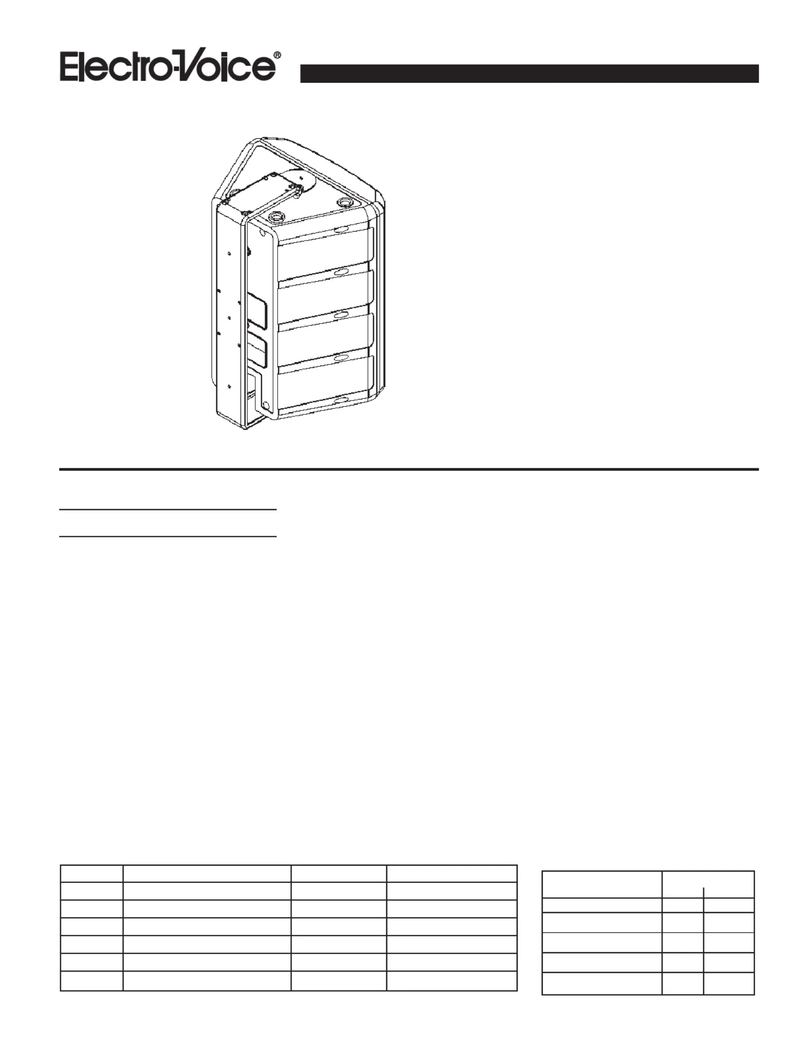
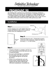
Wall or Ceiling Mounting:
The robust design of the M
b
200 installation
bracket allows the System 200
TM
speakers
to be mounted in almost any position to ob-
tain the desired sound coverage (see Figure
3).
Flying Installations
The M
b
200 bracket “captures” the speaker
in a rigid frame which has structurally sound
locations for attaching rigging hardware.
These attachment points are four 12.7-mm
(
1
/
2
-in.) diameter holes located on the ends
of the bracket. A
3
/
8
-in. “quick link” (or simi-
lar hardware) can be readily connected to
each attachment point.
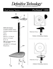
System 200
TM
speakers can be own indi-
vidually in either a horizontal or vertical po-
sition, or two speakers can be flown together
in a vertical position (see Figures 4 and 5).
System 200
TM
Horizontal Arrays
Arrays of two to six speakers are securely
supported in a frame comprised of M
b
200
and M
b
300 brackets. To create a horizontal
array, two M
b
200 brackets are simply locked
into the correct alignment position using the
brackets from the M
b
300 Horizontal Array
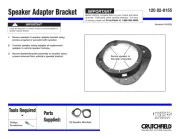
Mb200
And Mb200W
Installation Kit
•Mounting kit for System
TM
200
speakers
•May be used in conjuction with
OmniMount
®
Series 100 support
system
1
•Versatile design allows the
speaker to be aimed at any angle
from wall or ceiling
•Provides a rigid frame for ying
one or two speakers
•Creates arrays of two to six speak-
ers when used with the M
b
300
Horizontal Array Kit
Kit (see Figure 6). The array is extended by
using one additional M
b
200 bracket and one
M
b
300 kit for each additional speaker. To
complete the circle for a six speaker array,
one additional M
b
300 kit is required. Please
refer to Chart 2 to select the exact number of
each kit needed, based on desired array size.
(Note: refer to M
b
300 Horizontal Array Kit
engineering data sheet for detailed instruc-
tions on System 200
TM
horizontal array con-
struction using M
b
200 Installation and
M
b
300 Horizontal Array Kits.)
Item Description Quanity Part Number
A Bracket 1 71914
B M8 x 1.25 hex head bolt 2 63310
C 5/16 split ring lock washer 2 38144
D 3/8-24 hex head bolt 2 63311
E 3/8 split ring lock washer 2 38834
F Friction washer 2 38829
CHART 2: Kit Requirements for
System 200
TM
Horizontal
Array Construction
CHART 1: M
b
200 Installation Kit Parts List
Produkspesifikasjoner
| Merke: | Electro-Voice |
| Kategori: | høyttalerstøtte |
| Modell: | MB200 |
Trenger du hjelp?
Hvis du trenger hjelp med Electro-Voice MB200 still et spørsmål nedenfor, og andre brukere vil svare deg
høyttalerstøtte Electro-Voice Manualer
7 August 2025

6 August 2025

16 Oktober 2024
høyttalerstøtte Manualer
- Harman Kardon
- B-tech
- Konig & Meyer
- SoundTube
- Yamaha
- Cambridge
- Hama
- Bogen
- Samson
- Vimar
- NeoMounts
- Valcom
- Definitive Technology
- Nubert
- Blaupunkt
Nyeste høyttalerstøtte Manualer
16 Oktober 2025
12 Oktober 2025
12 Oktober 2025
12 Oktober 2025
10 Oktober 2025
9 Oktober 2025
9 Oktober 2025
9 Oktober 2025
9 Oktober 2025
9 Oktober 2025