Festo CASM-S-D2-R3 Bruksanvisning
Festo
Ikke kategorisert
CASM-S-D2-R3
Les nedenfor 📖 manual på norsk for Festo CASM-S-D2-R3 (2 sider) i kategorien Ikke kategorisert. Denne guiden var nyttig for 15 personer og ble vurdert med 5.0 stjerner i gjennomsnitt av 8 brukere
Side 1/2
Warnung, Warning, ..............................
de Verletzungsgefahr durch unkontrollierte Bewegungen
der Aktorik!
Schalten Sie vor Installations- und Wartungsarbeiten
die Energiequellen in folgender Reihenfolge ab:
1. Druckluftversorgung
2. Spannungsversorgung
en Sudden uncontrolled movements of the actuators can
cause injury to human beings.
Before carrying out installation and/or maintenance
work, switch off the following sources of energy in the
sequence specified:
1. the compressed air supply
2. the power supply.
zh 。
, /
!:
1. #$% &
2. 。'!
Bild 1 / Fig. 1 / ()* 1
4
5
6
1 2 3
Bild 2 / Fig. 2 / ()* 2
77
S1
S2
7
Bild 3 / Fig. 3 / ()* 3
Bild 4 / Fig. 4 / ()* 4
8
S1
S2
Sensorinterface de ................................................
CASM-S-D2-R3
1 Bestimmungsgemäße Verwendung
Das Sensorinterface CASM-S-D2-R3 dient bestimmungsge
mäß zur Anschaltung pneumatischer Antriebe mit analogem
Wegmesssystem an einen Positioniercontroller von Festo
(z. B. Typ CMAX oder CMPX).
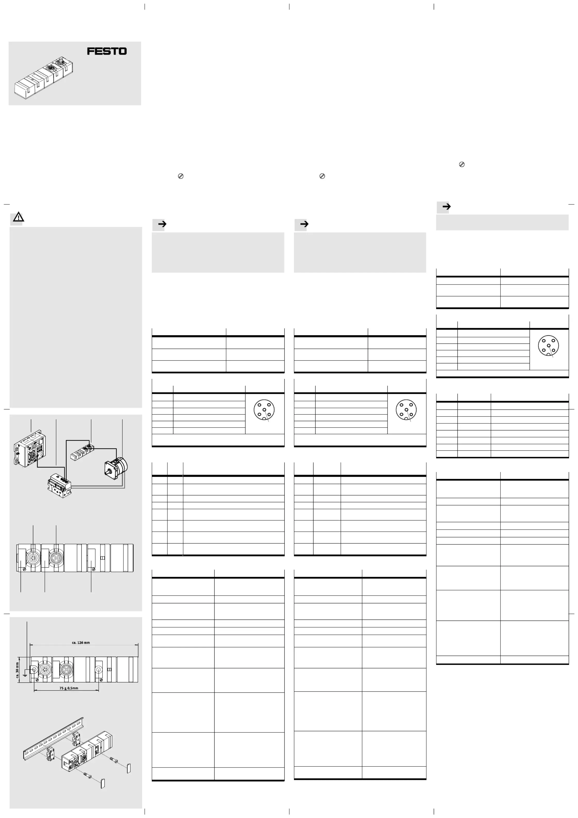
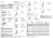
Es stellt die Verbindung zwischen Wegmesssystem und einem
Proportional-Wegeventil VPWP her, siehe Bild 1:
1Positioniercontroller CMAX oder Soft Stop CMPX
2Proportional-Wegeventil VPWP
3Sensorinterface CASM-S-D2-R3
4Antrieb mit Wegmesssystem (Potentiometer, hier DSMI)
2 Anschluss- und Anzeigeelemente
Siehe Bild 2:
5S1: Anschluss für VPWP (mit LED grün)
6S2: Anschluss für Wegmesssystem (mit LED rot)
7Bezeichnungsschilder ISB-8x20 (Zubehör)
3 Montage
Befestigen Sie den CASM-S-D2-R3 auf einer ebenen Fläche
mit zwei Schrauben M4 und jeweils einer Sicherungsscheibe,
siehe Bild 3.
Anziehdrehmoment: 2 ±0,5 Nm.
Das Symbol kennzeichnet die Lage der Befestigungs
schrauben. Die äußere Befestigungsschraube dient gleichzei
tig zur Erdung (
8 ).
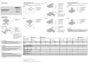
Die Befestigung auf Hutschienen nach EN 60715 ist mit dem
Montagesatz Typ CP-TS-HS35 möglich, siehe Bild 4.
4 Installation
Hinweis..................................................
Störungen durch elektromagnetische Einflüsse können die
Messergebnisse verfälschen und falsche Positionen
vortäuschen.
Beachten Sie die folgenden Hinweise, um Störungen
durch elektromagnetische Einflüsse zu vermeiden.
Verwenden Sie nur die Originalkabel (siehe Tabelle).
Verlängern Sie die Kabel nicht.
Ein Verlängern der Kabel senkt die Störfestigkeit.
Verlegen Sie die Kabel nicht in der Nähe oder parallel zu
Leitungen mit hohem Störpegel.
Fixieren Sie die Stecker mit Hilfe der Überwurfmutter.
Verbinden Sie den Erdungsanschluss ( 8 ) niederohmig
mit dem Erdpotenzial.
Verbindung zu Kabel Typ
Proportional-Wegeventil
VPWP-...
KVI-CP-3-...
Wegmesssystem MLO-POT-...-LWG
oder Schwenkmodul DSMI-...
NEBC-P1W4-K-0,3-N-M12G5
Wegmesssystem MLO-POT-...-TLF
oder Positionierantrieb DNCM
NEBC-A1W3-K-0,3-N-M12G5
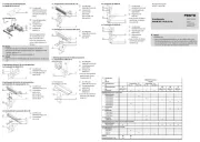
Messsystem-Schnittstelle S2 ( 6 )
Pin Belegung Anschluss S2
1 Gehäuse Messsystem
3
2
4
1
5
2 n.c. (nicht verbunden)
3 Analog GND (AGND)
4 Referenzspannung (REF)
5 Analoger Eingang (INPUT)
Gehäuse Erdungsanschluss (FE)
Kabelschirm wird auf Erdungsanschluss des Sensorinterface geführt.
5 Diagnose
LED
S1
LED
S2
Zustand
aus aus 24 V nicht vorhanden
blinkt
grün
rot 24 V vorhanden
grün rot Initialisieren über CAN abgeschlossen
grün aus Betriebsbereit ohne Fehler
grün blinkt
rot 1x
Sensorfehler
grün blinkt
rot 2x
Kabelbruch Sensorkabel oder elektrische Endlage
erreicht
grün blinkt
rot 3x
Versorgungsspannung < 17 V für länger als 15 ms
grün blinkt
rot 4x
CAN-Kommunikation gestört: Bus Off Zustand
6 Technische Daten
Typ
CASM-S-D2-R3
Maße (ohne Stecker) Breite: ca. 30 mm
Höhe: ca. 34 mm
Länge: ca. 126 mm
Gewicht ca. 130 g
Temperaturbereich:
– Betrieb
– Lagerung/Transport
0 … +55 C
-20 … +70 C
Relative Luftfeuchtigkeit 95 %, nicht kondensierend
Schutzart nach EN 60529 IP65 und IP67 (angeschlossen)
Schockfestigkeit 30 g Beschleunigung bei 11 ms
Dauer
Schwingfestigkeit Transport
Schwingfestigkeit Betrieb
3,5 mm Weg bei 2…9Hz,
1 g Beschleunigung bei 9…200 Hz
0,35 mm Weg bei 10…60 Hz,
5 g Beschleunigung bei 60…150 Hz
CE-Zeichen (siehe Konformität
serklärung)
1)
è www.festo.com/sp
nach EU-EMV-Richtlinie
– Max. Leitungslänge 30 m
Ventilanschluss
– Ausführung
– Spannungsversorgung
– Restwelligkeit
– Stromaufnahme bei Nenn
betriebsspannung
– Anforderungen an die Span
nungsversorgung Elektronik
M9 Anschluss, Stift, 5-polig
24 V
±25 %
4 Vss bei 50 Hz
40 ... 50 mA
Netzteil gemäß PELV Richtlinie
Messsignal
– Ausführung
– Spezifikation Analogeingang
– Linearität
– Referenzspannung
– Aktiver Messbereich
M12 Anschluss, Dose, 5-polig
nach EN 61131-2
< 0,5 % (ohne Berücksichtigung des
Potentiometer-Linearitätsfehlers)
5 V
0,015 … 4,985 V
Galvanische Trennung:
CAN-Bus/Messsignal
nein
1) Das Gerät ist für den Einsatz im Industriebereich vorgesehen.
Außerhalb von industriellen Umgebungen, z.B. in Gewerbe- und Wohn-
Mischgebieten, müssen evtl. Maßnahmen zur Funkentstörung getroffen
werden.
Sensor interface en. . . . . . . . . . . . . . . . . . . . . . . . . . . . . .
CASM-S-D2-R3
1 Designated use
The sensor interface CASM-S-D2-R3 has been designed to be
used for connecting pneumatic drives with analogue measur
ing system to a positioning controller from Festo (e. g. type
CMAX or CMPX).
It provides the connection between the measuring system and
a proportional directional control valve type VPWP, seeFig. 1:
1Positioning controller CMAX or Soft Stop CMPX
2Proportional directional control valve VPWP
3Sensor interface CASM-S-D2-R3
4Drive with measuring system (potentiometer, here DSMI)
2 Connection and display elements
See Fig. 2:
5S1: Connection for VPWP (with green LED)
6S2: Connect. for measuring system (with red LED)
7Identification labels ISB-8x20 (accessories)
3 Mounting
Fasten the CASM-S-D2-R3 on a flat surface with two M4
screws each with a retaining washer, see Fig. 3.
Tightening torque: 2 ±0.5 Nm.
The symbol marks the position of the fastening screws.
The outer fastening screw serves at the same time for
earthing (
8 ).
Fastening on hat rails as per EN 60715 is possible with
mounting kit type CP-TS-HS35, see Fig. 4.
4 Installation
Please note..............................................
Interference caused by electromagnetic influences can
falsify the measured results and simulate incorrect
positions.
Observe the following installation instructions in order
to avoid interference caused by electromagnetic
influences.
Use only the original cable (see table).
Do not extend the cables.
Extending the cables will reduce immunity to interference.
Do not place the cables near or parallel to cables with high
levels of interference.
Fasten the plugs with the aid of the union nut.
Connect the earthing connection ( 8 ) at low impedance to
the earth potential.
Connection to Cable type
Proport. direct. control valve
VPWP-...
KVI-CP-3-...
Measuring system MLO-POT-...-LWG
or swivel module DSMI-...
NEBC-P1W4-K-0,3-N-M12G5
Measuring system MLO-POT-...-TLF
or positioning drive DNCM
NEBC-A1W3-K-0,3-N-M12G5
Measuring system interface S2 ( 6 )
Pin Assignment Connection S2
1 Measuring system housing
3
2
4
1
5
2 n.c. (not connected)
3 Analogue GND (AGND)
4 Reference voltage (REF)
5 Analogue input (INPUT)
Housing Earthing connection (FE)
The cable screening is connected to the earthing terminal of the
sensor interface.
5 Diagnosis
LED
S1
LED
S2
Status
off off 24 V not available
flashes
green
red 24 V available
green red Initializing via CAN completed
green off Ready to operate without fault
green flashes
red once
Sensor fault
green flashes
red twice
Sensor cable interrupted or electrical end
position reached
green flashes
red 3times
Supply voltage < 17 V for longer than 15 ms
green flashes
red 4times
CAN communication interrupted: Bus Off
status
6 Technical specifications
Type
CASM-S-D2-R3
Dimensions (without plug) width: approx. 30 mm
height: approx. 34 mm
length: approx. 126 mm
Weights approx. 130 g
Temperature range:
– Operation
– Storage/transpor t
0 … +55 C
-20 … +70 C
Relative air humidity 95 %, non-condensing
Protection class as per EN60529 IP65 and IP67 (connected)
Shock resistance 30 g acceleration at 11 ms
duration
Resistance to vibration, transport
Resistance to vibration, operation
3.5 mm path at 2…9Hz,
1 g acceleration at 9…200 Hz
0,35 mm path at 10…60 Hz,
5 g acceleration at 60…150 Hz
CE marking (see declaration of
conformity)
1)
è www.festo.com/sp
in accordance with EU EMC
Directive
– Max. cable length 30 m
Valve connection
– Design
– Power supply
– Residual ripple
– Current consumption at rated
operating voltage
– Requirements of the power
supply for the electronics
M9 connection, pin, 5-pin
24 V
±25 %
4 Vpp at 50 Hz
40 ... 50 mA
power unit as per PELV
guideline
Measuring signal
– Design
– Specification for analogue input
– Linearity
– Reference voltage
– Active measuring range
M12 connection, socket, 5 pin
as per EN 61131-2
< 0.5 % (without regarding the
potentiometer linearity fault)
5 V
0.015 … 4.985 V
Electrical isolation:
CAN bus/measuring signal
no
1) The device is intended for use in an industrial environment. Outside of
industrial environments, e.g. in commercial and mixed-residential
areas, actions to suppress interference may have to be taken.
...............................
CASM-S-D2-R3
1
+,-. CASM-S-D2-R3
/01 2-% 3 ,456789,
Festo 。:;< CMAX CMPX) ,
> 6789 ;< ? VPWP
@ AB D2- ()* C 1:
1 , CMAX Soft Stop CMPX
2@ AB C VPWP
3+,-. CASM-S-D2-R3
467893 (' 0,FG DSMI)
2
()* 2:
5S1: 2- VPWP HIJ LED)
6S2: 2-6789 KJ LED)
7LMLN O ) ISB-8x20
3
1 HPQ M4 RST CASM-S-D2-R3
UVW ()* XYZ[: 3。 2 ±0.5 Nm.
\<L] L]YURS 。^
_`YURSab1-c (8)。
1d ;< ,e CP-TS-HS35 EN 60715
U fghij,()* 4。
4
...................................................
'klmno67pq r,s45 ^tu 。
ev wx yz {'klm。
。 1 '|(()*})
~ '|。 ~ '|T lm。
T'|^ {lm'|O V
。 1-RgU
T-c2- '2--c' (8) 。
@ AB C VPWP-... KVI-CP-3-...
6789 MLO-POT-...-LWG
X4 DSMI-...
NEBC-P1W4-K-0,3-N-M12G5
6789 MLO-POT-...-TLF
3 , DNCM
NEBC-A1W3-K-0,3-N-M12G5
S2 (6) ( 6 )
S2
16789_
3
2
4
1
5
22-
345 GND (AGND)
4(' (REF)
5 (INPUT)45 ( )
_ -c2- (FE)
'|2- +,-.-c 。
5
LED S1
LED S2
24 V 1
IJ J 124 V
IJ J o CAN
IJ ,
IJ J
IJ J +,'| ¡'%¢ ^
IJ J '!' £¤ 3 < 17 V 15 ms
IJ J ¥ : ¦§ ¨©ª 4 CAN
6技术规格
CASM-S-D2-R3
«¬( ) ®¯: ° 30 mm
±¯: ° 34 mm
²¯: ° 126 mm
³7 ° 34 mm
´¯µ¶:
–
–/
0 ... +55 ºC
-20 ... +70 ºC
·¸$%¹¯ ,º95 %
e » (¼2-) EN 60529 IP65 IP67
½ ¾¿ À¯ 11 ms 30 g
Á½,
Á½,
3.5 mm 2 ... 9 Hz, ÂÃ
1 g 9 ... 200 HzÀ¯
0.35 mm 10 ... 60 Hz, ÂÃ
5 g 60 ... 150 HzÀ¯
CeLÄ
() Å ½Æx) ) 1
è
www.festo.com/sp
\ÇÈ'k ɽ
-Ê˧²¯ 30 м
C2-
–
–
–
–
–
M9 、 、5 2- ÌÍ ÌÍ
24 V
±25 %
4 Vpp at 50 Hz
40 ... 50 mA
\ '!` PELV
67 <
–
– !"#$
–%&
–'(
–)*+,-
M12 、 、5 2- Î ÌÍ
e EN 61131-2
< 0.5 %
( Ï' 0§½uÐ)
5 V
0.015 ... 4.985 V
'ÑÒ: ¦§ 67 <CAN /
1) Ó/ 1 ÔÕ 。
Ö ×Ø_, :: ÙÚ ,ÛÜÝÞßàyz
§'lm。
CASM-S-D2-R3
Kurzbeschreibung
Brief description
áâ
Original: de
Festo SE & Co. KG
Postfach
D-73726 Esslingen
Phone:
+49/711/347-0
www.festo.com
8043264
1505b
[8043265]
Produkspesifikasjoner
| Merke: | Festo |
| Kategori: | Ikke kategorisert |
| Modell: | CASM-S-D2-R3 |
Trenger du hjelp?
Hvis du trenger hjelp med Festo CASM-S-D2-R3 still et spørsmål nedenfor, og andre brukere vil svare deg
Ikke kategorisert Festo Manualer
6 August 2025
6 August 2025
6 August 2025
6 August 2025
6 August 2025
6 August 2025
6 August 2025
6 August 2025

31 Mars 2025

31 Mars 2025
Ikke kategorisert Manualer
- Rocketfish
- Lofrans
- Duravit
- Victor Technology
- Tilta
- Blood Cells Audio
- Amica
- UGo
- Ghibli & Wirbel
- Elica
- Auna
- Amana
- Berker
- EMeet
- Karran
Nyeste Ikke kategorisert Manualer

23 Oktober 2025

23 Oktober 2025

23 Oktober 2025

23 Oktober 2025

23 Oktober 2025

23 Oktober 2025

23 Oktober 2025

23 Oktober 2025

23 Oktober 2025

23 Oktober 2025