Festo ELCC-TB-KF-90-1500-0H-P0-CR Bruksanvisning
Festo
Ikke kategorisert
ELCC-TB-KF-90-1500-0H-P0-CR
Les nedenfor 📖 manual på norsk for Festo ELCC-TB-KF-90-1500-0H-P0-CR (30 sider) i kategorien Ikke kategorisert. Denne guiden var nyttig for 22 personer og ble vurdert med 4.7 stjerner i gjennomsnitt av 11.5 brukere
Side 1/30
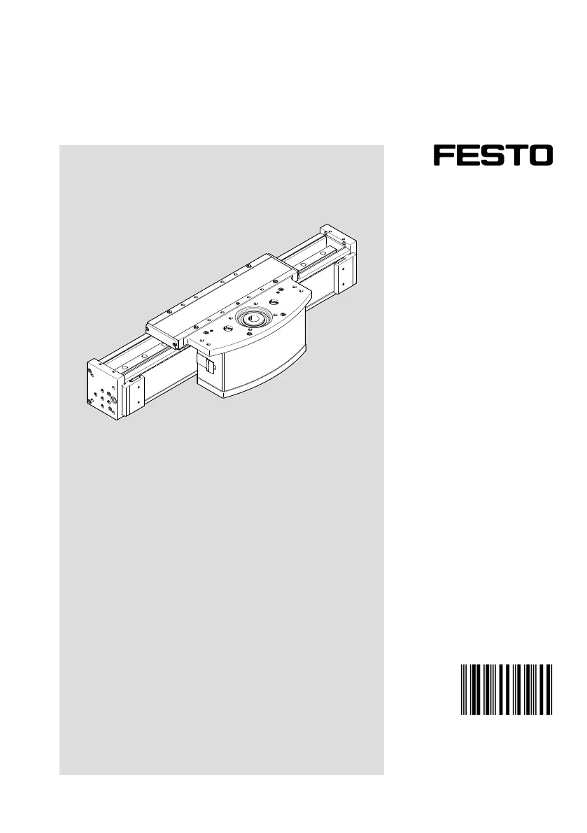
ELCC-TB
Cantilever axis
Operating instruc-
tion
8178817
8178817
2023-05c
[8178819]
Produkspesifikasjoner
| Merke: | Festo |
| Kategori: | Ikke kategorisert |
| Modell: | ELCC-TB-KF-90-1500-0H-P0-CR |
Trenger du hjelp?
Hvis du trenger hjelp med Festo ELCC-TB-KF-90-1500-0H-P0-CR still et spørsmål nedenfor, og andre brukere vil svare deg
Ikke kategorisert Festo Manualer
6 August 2025
6 August 2025
6 August 2025
6 August 2025
6 August 2025
6 August 2025
6 August 2025
6 August 2025

31 Mars 2025

31 Mars 2025
Ikke kategorisert Manualer
- Xlyne
- BlueBuilt
- Core SWX
- Galcon
- Stelton
- Audio Pro
- RC Allen
- Bang And Olufsen
- Merlin
- Crown Verity
- Oster
- LevelOne
- EBERLE
- Kyocera
- Bestron
Nyeste Ikke kategorisert Manualer

23 Oktober 2025

23 Oktober 2025

23 Oktober 2025

23 Oktober 2025

23 Oktober 2025

23 Oktober 2025

23 Oktober 2025

23 Oktober 2025

23 Oktober 2025

23 Oktober 2025