Festo OVEM-14-H-B-QO-CE-N-1PD Bruksanvisning
Festo
Ikke kategorisert
OVEM-14-H-B-QO-CE-N-1PD
Les nedenfor 📖 manual på norsk for Festo OVEM-14-H-B-QO-CE-N-1PD (50 sider) i kategorien Ikke kategorisert. Denne guiden var nyttig for 19 personer og ble vurdert med 4.9 stjerner i gjennomsnitt av 10 brukere
Side 1/50
8125662
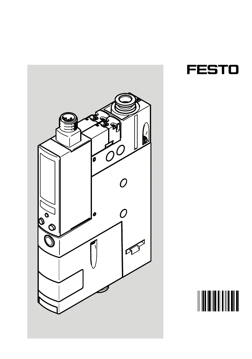
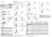
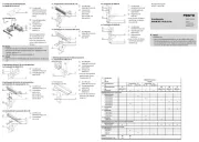
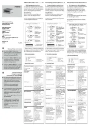
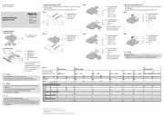
OVEM
Vacuum generator
8125662
2020-05h
[8125664]
Operating instructions
Produkspesifikasjoner
| Merke: | Festo |
| Kategori: | Ikke kategorisert |
| Modell: | OVEM-14-H-B-QO-CE-N-1PD |
Trenger du hjelp?
Hvis du trenger hjelp med Festo OVEM-14-H-B-QO-CE-N-1PD still et spørsmål nedenfor, og andre brukere vil svare deg
Ikke kategorisert Festo Manualer
6 August 2025
6 August 2025
6 August 2025
6 August 2025
6 August 2025
6 August 2025
6 August 2025
6 August 2025

31 Mars 2025

31 Mars 2025
Ikke kategorisert Manualer
- Söll
- NordicTrack
- Jinbei
- Violectric
- DoorBird
- Playtive
- Atlas
- Sure Petcare
- Best
- MasterCraft
- Vixen
- Dracast
- SurgeX
- Playseat
- Kichler
Nyeste Ikke kategorisert Manualer

23 Oktober 2025

23 Oktober 2025

23 Oktober 2025

23 Oktober 2025

23 Oktober 2025

23 Oktober 2025

23 Oktober 2025

23 Oktober 2025

23 Oktober 2025

23 Oktober 2025