Festo SBA-2N-PK-3 Bruksanvisning
Festo
Ikke kategorisert
SBA-2N-PK-3
Les nedenfor 📖 manual på norsk for Festo SBA-2N-PK-3 (4 sider) i kategorien Ikke kategorisert. Denne guiden var nyttig for 15 personer og ble vurdert med 5.0 stjerner i gjennomsnitt av 8 brukere
Side 1/4
Operating instructions
Notice
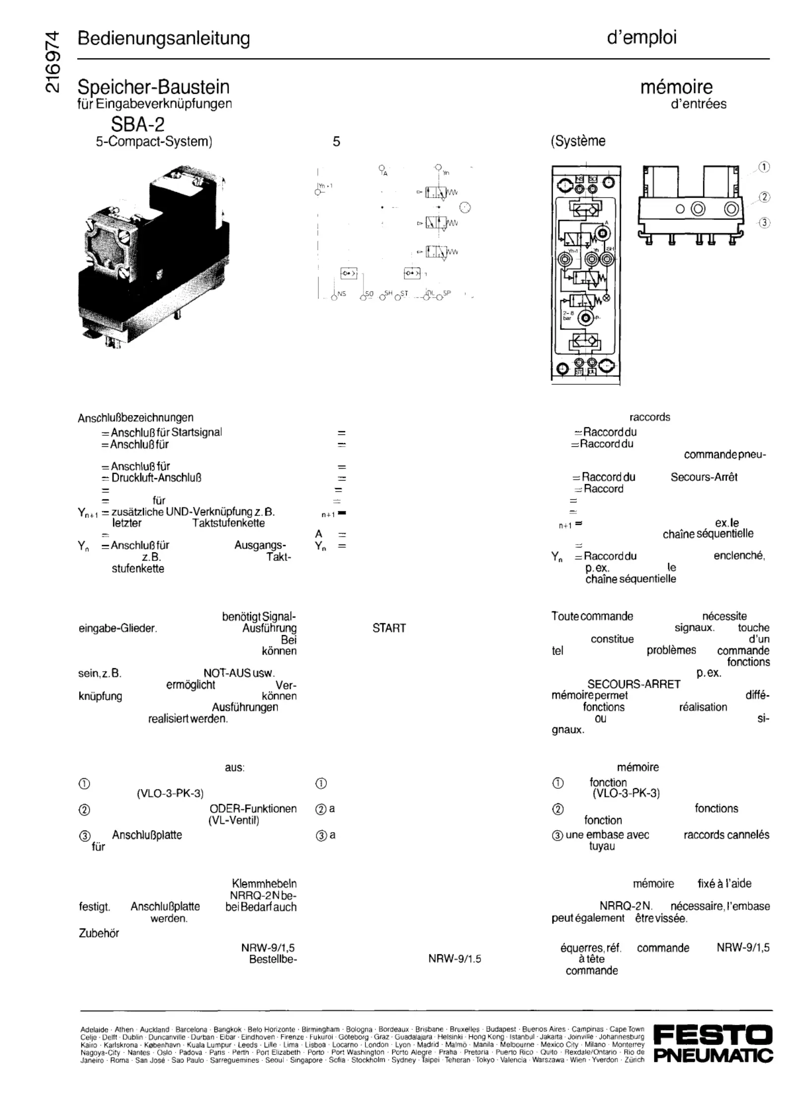
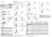
Typ
N-PK-3
(M
ST
s o
NS
P
SH
DL
A
(Typenschild):
Haltsignal
(Steuerung in Grundstellung)
Not-Aus-Signal
Ausgang zur Selbsthaltung
Eingang
Selbsthaltung
Takt einer
Ausgangssignal
geschaltetes
signal
zum ersten Takt einer
Anwendung
Jede pneumatische Steuerung
Die einfachste
der Signaleingabe ist eine START-Taste.
umfangreichen Steuerungsaufgaben
mehrere Signaleingabe-Funktionen notwendig
START, HALT,
Der
Speicher-Baustein
die einfache
dieser Funktionen. Mit ihm
einfache und umfangreiche
der
Signaleingabe
Aufbau
Der Speicher-Baustein besteht
einer UND-Funktion (VL-3-PK-3) und einer
Inhibition
einer Logikplatte mit zwei
und einer UND-Funktion
der
mit neun Stecknippeln
Kunststoschlauch NW 3
Montage
Der Speicher-Baustein wird mit
auf dem Montagerahmen Typ
Die
kann
festgeschraubt
fur Schraubbefestigung:
2 Winkel Bestellbezeichnung 5658
2 Zylinderschrauben M 4x10, DIN 84
zeichnung 200525.
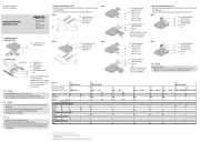
Memory module
for linking inputs
Type SBA-2 N-PK-3
(M
Compact System)
Connection designations (type plate):
ST
Connection for start signal
SO
Connection for stop signal
(normal position of pneumatic control)
NS
Connection for emergency o signal
P
Connection for compressed air
SH
Latching output
DL
Latching input
Y
Additional AND gate, e.g. the last step
of a shift register chain
Output signal
Connection for switched output signal,
e.g. input to the rst step of a shift
register chain
Application
Every pneumatic control requires signal input
elements. A
push button is the simplest
type of input element. Complex control tasks,
however, may require several signal input
functions such as START, STOP, EMERGEN-
CY OFF, etc. This memory module enables
the simple linking of such functions, so that
both simple and complex types of signal input
can be realized.
Design
The memory module consists of:
an AND function (VL-3-PK-3) and an inhi-
bitor (VLO-3-PK-3)
logic plate with two OR functions and an
AND function (VL valve)
sub-base with new serrated nipples for
plastic tubing of size NW 3
Mounting
The memory module is mounted on mounting
frame type NRRQ-2N by means of clamping
levers. The sub-base can also be mounted
using screws if desired.
Accessories for screw mounting:
2 angle brackets,
order designation: 5658
2 llister-head screws, M 4 x 10, DIN 84,
order designation: 200525.
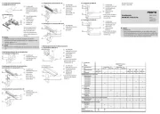
Module de
pour la combinaison
Type SBA-2 N-PK-3
Compact M 5)
Designation des
(plaquesignaletique):
ST
signal Start
SO
signal Stop
(position initiale pour
matique)
NS
signal
P
d’alimentation
SH Sortie de verrouillage
DL Entree de verrouillage
Y
Porte ET supplementaire p.
dernier pas d’un
A
Signal de sortie
signal de sortie
entree pour
premier pas d’une
Application
pneumatique des
elements d’introduction de
Une
START
la version la plus simple
element. Des de
complexes exigent toutefois plusieurs
d’introduction des signaux,
START,
STOP,
etc. Ce module de
la combinaison de ces
rentes
ainsi que la
de types
simples
complexes d’introduction de
Structure
Le module de
comprend:
Une
ET (VL-3-PK-3) et une inhi-
bition
une plaque logique a deux OU et
une
ET (distributeur VL)
neuf
pour
plastique DN 3
Montage
Le module de
est
de
leviers de serrage sur les cadres de montage
de type
Si
y
Accessoires pour xation par vis:
2
de
5658
2 vis
cylindrique M 4 x 10, DIN 84, ref.
de
200 525.
Produkspesifikasjoner
| Merke: | Festo |
| Kategori: | Ikke kategorisert |
| Modell: | SBA-2N-PK-3 |
Trenger du hjelp?
Hvis du trenger hjelp med Festo SBA-2N-PK-3 still et spørsmål nedenfor, og andre brukere vil svare deg
Ikke kategorisert Festo Manualer
6 August 2025
6 August 2025
6 August 2025
6 August 2025
6 August 2025
6 August 2025
6 August 2025
6 August 2025

31 Mars 2025

31 Mars 2025
Ikke kategorisert Manualer
- Futaba
- UNYKAch
- Prime3
- Vestil
- 2hp
- Comfee
- Gamesir
- Dexibell
- Kluge
- Trixie
- Indesit
- Ariete
- Sole Fitness
- PreSonus
- Truetone
Nyeste Ikke kategorisert Manualer

23 Oktober 2025

23 Oktober 2025

23 Oktober 2025

23 Oktober 2025

23 Oktober 2025

23 Oktober 2025

23 Oktober 2025

23 Oktober 2025

23 Oktober 2025

23 Oktober 2025