Festo VAME-T-M5 Bruksanvisning
Festo
Ikke kategorisert
VAME-T-M5
Les nedenfor 📖 manual på norsk for Festo VAME-T-M5 (2 sider) i kategorien Ikke kategorisert. Denne guiden var nyttig for 21 personer og ble vurdert med 4.7 stjerner i gjennomsnitt av 11 brukere
Side 1/2

Montageanleitung (Original: de)
8038045
1407a
†‡
Hutschienenbefestigung
VAME-T-M5
Festo SE & Co. KG
Postfach
73726 Esslingen
Deutschland
+49 711 347-0
www.festo.com
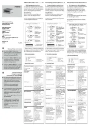
1. Te
ileliste
18
38
2d
_1
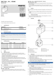
1 Hutschienen-
befestigung
VAME-T-M5
(2x)
18
38
2d
_2
Nicht im Lieferumfang:
2 Hutschiene
EN 60715 TH35x15
3 Ventilinsel
(1x)
(1x)
VTUB-12/VTUG/VTUS
4 Schraube
( Tabelle)
5 Anschlussleiste
(2x)
(1x)
VABM-C8-.../-L1-.../-B10-...
2. Bestimmu
ngsgemäße Verwendung
Hutsch
ienenbefestigung VAME-T-M5:
Befestigung der Ventilinsel 3 an die Hutschiene 2.
3. Sicherheitshinweise und Hinweise zur Montage
Vorsicht
Unerwartete Bewegung von Bauteilen
Verletzung durch Schlag, Stoß, Quetschung
Stromversorgung und Druckluft vor Montagearbeiten abschalten.
Sicherheitshinweise beachten ( Kurzbeschreibung VTUB-12/VTUG).
Hinweis
Funktionsstörung und Sachschaden durch unsachgemäße Montage.
Schwing-Schock-Belastung bei dieser Befestigungsart vermeiden.
Hutschiene horizontal montieren.
Hutschiene nicht überlasten
Technische Daten www.festo.com/catalogue: VTUB-12/VTUG/VTUS
Zulässige Belastungen der Hutschiene EN 60715 TH35x15
Sachgemäß montieren ( Abschnitt 4).
Sachschaden durch abfallende Ventilinsel 3.
Sachgemäß demontieren ( Abschnitt 5).
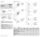
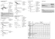
4. Montage
18
38
2d
_3
Hutschiene 2 montieren.
Klammern (A) nach unten
ausrichten.
Befestigungen 1 an der An-
schlussleiste 5 platzieren.
Nur bei Anschlussblock
VABM-B1
0-25S
-...-P3:
Bohrungen (B) am schmalen
Abstand der Stege (C) ver-
wenden.
Schrauben 4 durch
die un-
teren Bohrun
gen (B) und in
die Befestigungen 1 drehen
bis Befestigungen 1 an der
Anschlussleiste 5 anliegen.
18
38
2d
_4
18
38
2d
_5
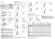
Haken (B) auf die Hutschie-
ne 2 hängen.
Ventilinsel 3 nach unten
kippen bis die Klammern (A)
einrasten.
18
38
2d
_6
Schrauben 4 festdrehen.
Anziehdrehmoment einhal-
ten.
Info
Durch das Festdrehen der
Schrauben 4 stellen sich die
Befestigungen 1 schräg. Die
Ventilinsel 3 verklemmt und
ist gegen Kippen und Verrut-
schen gesichert.
Befestigungen 1 nicht richten.
18
38
2d
_1
0
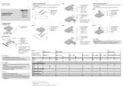
5. Demontage
18
38
2d
_7
Anschlüsse von der Ventil-
insel 3 entfernen.
Schrauben 4 maximal
2 Umdrehungen aufdre-
hen ( Hinweis).
18
38
2d
_8
Ventilinsel 3 nach oben
kippen bis die Klammern (A)
ausrasten.
18
38
2d
_9
Ventilinsel 3 von der Hut-
schiene heben.
6. Zulässige Anschlussleisten 5
5
5
55, S
chraubengrößen , Ventilplätze (VP)
4
4
4
44
VABM-C8-... VTUB-12 4
4
4
44 Schraube
1
)
Nm 2
2
2
22
TH35-15
12E 12 M5x40 2 ± 25 % ≤ 35 VP
VABM-L1-... VTUG-... 4
4
4
44 Schraube
1
)
Nm 2
2
2
22
TH35-15
18 18 M5x55 2 ± 25 % ≤ 24 VP
VABM-B10-... VTUS-... 4
4
4
44 Schraube
1
)
Nm 2
2
2
22
TH35-15
25E-...12 25 M5x55 2 ± 25 % ≤ 12 VP
25E-...-P3
25S-...38 M5x45 1,5 ± 20 %
25S-...-P3
1)
Länge der Schraube 4 ± 0,5 mm
B
3
A
1
3
A
3
2
4
4
4
4
4
1
2
A
1
4
5
B
C
1
3
5
2
4
Produkspesifikasjoner
| Merke: | Festo |
| Kategori: | Ikke kategorisert |
| Modell: | VAME-T-M5 |
Trenger du hjelp?
Hvis du trenger hjelp med Festo VAME-T-M5 still et spørsmål nedenfor, og andre brukere vil svare deg
Ikke kategorisert Festo Manualer
6 August 2025
6 August 2025
6 August 2025
6 August 2025
6 August 2025
6 August 2025
6 August 2025
6 August 2025

31 Mars 2025

31 Mars 2025
Ikke kategorisert Manualer
- Scala
- Marmitek
- Zenec
- Sanus
- Vox
- Baofeng
- Korg
- Xlyne
- RTS
- Vivolink
- Kiloview
- SSV Works
- Technaxx
- PCE Instruments
- Nacon
Nyeste Ikke kategorisert Manualer

23 Oktober 2025

23 Oktober 2025

23 Oktober 2025

23 Oktober 2025

23 Oktober 2025

23 Oktober 2025

23 Oktober 2025

23 Oktober 2025

23 Oktober 2025

23 Oktober 2025