Lutron RMJS-8TN-DV-B Bruksanvisning
Les nedenfor 📖 manual på norsk for Lutron RMJS-8TN-DV-B (8 sider) i kategorien Dimmer. Denne guiden var nyttig for 15 personer og ble vurdert med 4.4 stjerner i gjennomsnitt av 8 brukere
Side 1/8

Radio Powr Savr
Occupancy
Sensor
Pico
Remote
Control
PowPak
Dimming
Module
30 ft
(9 m) max
40 ft (12 m)
33 ft (10 m)
PowPak
Dimming Module
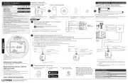
Install in center of room to
maximize RF coverage.
A
Connect mains wiring (switched hot, neutral) to each fixture.
B
Connect 0 –10 V- control (+ and – ) to each fixture.
1
+
–
NEU
HOT
Class 2
MAINS
Fixture Earth
Green/Yellow
To additional 0 –10 V- fixtures
Neutral
Switched Line/Hot
Violet
Gray
+
–
WARNING! Shock Hazard. May result in serious injury or death. Turn off power at circuit
breaker before installing the unit.
Sample
ballast shown
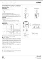
Start Here
Mount, Wire, and Install 0 –10 V- Devices
and Lighting Fixtures
Consult third-party device installation guide
2
A
PowPak Dimming Module with 0 –10 V- can be installed in a junction box or marshalling box using the conduit nut (provided) or with mounting
screws (not provided). Please consult local and national electric codes for proper installation.
If installing unit inside a junction box, please see Application Note #423 (P/N 048423 at www.lutron.com).
B
Once installed, energize the PowPak Dimming Module with 0 –10 V-.
C
Use the Toggle button “ u” to toggle between high-end and OFF to verify ballast wiring.
D
Use the Raise “
ŷ
” and Lower “
Ǻ
” buttons to verify control wiring.
Install PowPak Dimming Module with 0 –10 V-
Suggested Installation Location: Center of room to ensure proper RF coverage of area.
Switched Line/Hot (Red)
–
Line/Hot
(Black)
To Fixtures
0 –10 V- to Fixtures*
Neutral (White)
+
Neutral
Junction Box
1/2 in (21 mm) Knockout Opening
Conduit Nut
RMJS-8T-DV-B / URMJS-8T-DV-B
Switched Line/Hot (Red)
–
Line/Hot
(Black)
To Fixtures
0 –10 V-
to Fixtures *
Neutral (White)
+
Neutral
Junction Box
1/2 in (21 mm) Knockout Opening
Conduit Nut
RMJS-8TN-DV-B
Switched Line/Hot (Red)
–
Line/Hot (Black)
To Emergency
Fixtures
0 –10 V- to
Emergency
Fixtures*
Neutral (White)
+
Neutral
Junction Box
1/2 in (21 mm)
Knockout Opening
Conduit Nut
Emergency
Backup
Generator
Automatic
Transfer
Switch
Regular
Utility Power
Neutral
120 / 277 V~ Normal Feed
Neutral
120 / 277 V~ Emergency Feed
Note: For periodic testing and maintanance of emergency systems, use the toggle button of
the RMJS-8T-DV-B-EM to ensure proper operation. Make sure PowPak buttons remain
accessible.
Note: Momentary power outages can envoke emergency mode on the dimming module. See
Troubleshooting section for details.
RMJS-8T-DV-B-EM
* Use 18 AWG to 16 AWG (0.75mm
2
to 1.5mm
2
) solid wire only
vive.lutron.com
X
Programming with a Vive Hub
3
A
Use an iOS® or Android®
compatible device.
C
Open the app and
follow the instructions.
Note: For further information on set
up, programming, and troubleshooting
with a Vive system, please refer to the
installation instructions included with the
Vive hub or visit www.lutron.com/vive
Note: For programming the PowPak
Dimming Module without a Vive hub
see reverse side.
X
Vive
B
Download the Lutron
Vive app.
041588
Rev. A
03/2018
PowPak | Installation
Dimming Module with 0 –10 V-
English
All Wireless
Transmitters must
be installed within 30 ft
(9 m) of the PowPak Dimming
Module with 0 –10 V-.
0 –10 V- Control: 10 V- 60 mA
UL 2043 Plenum Rated
UL 924 Listed (RMJS-8T-DV-B-EM)
Compatible with ANSI E1.3 2001 (R2006), IEC 60929 Annex E
120 / 277 V~ 50 / 60 Hz 8 A
RMJS-8T-DV-B
URMJS-8T-DV-B
RMJS-8TN-DV-B
Important Notes: Please read before installing.
For installation by a qualified electrician in accordance with all local and
national electrical codes (including periodic testing and maintenance of
emergency systems).
• Note: Use copper conductors only.
• Check to see that the device type and rating is suitable for the application.
• DO NOT install if product has any visible damage.
• If moisture or condensation is evident, allow the product to dry completely
before installation.
• Operate between 32 °F and 104 °F (0 °C and 40 °C) ambient.
• 0% to 90% humidity, non-condensing.
• For indoor use only.
Note for Replacement:
RMxS and URMxS - the "S" model can replace the non-"S" model
041646
Rev. A
03/2018
Part of the Vive Family
120 / 277 V~ 50 / 60 Hz 8 A
RMJS-8T-DV-B-EM
IMPORTANT SAFEGUARDS
When using electrical equipment, basic safety precautions should always be
followed including the following:
READ AND FOLLOW ALL SAFETY
INSTRUCTIONS.
• Do not use outdoors.
• Do not mount near gas or electric heaters.
• Equipment should be mounted in locations and at heights where it will not be
subjected to tampering by unauthorized personnel.
• The use of accessory equipment not recommended by the manufacturer may
cause an unsafe condition.
• Do not use this equipment for other than its intended use.
SAVE THESE INSTRUCTIONS
Test
Link
Cal.
+
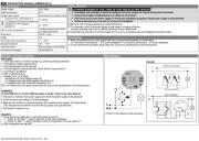
For each system, ensure that you have:
One PowPak Dimming Module At least one Wireless Transmitter At least one 0 –10 V- Fluorescent Ballast or LED Driver
Required Components
Radio Powr Savr Occupancy/Vacancy Sensor
(10 maximum)
Radio Powr Savr Daylight Sensor
(1 maximum)
Pico Remote Control
(10 maximum)
60 mA maximum for the control lines. Switches up to 8 A total.
May be pre-installed in light fixture.
Note: All drivers and ballasts used with Vive wireless controls must comply with the
limits for a Class A device, pursuant to Part 15 of the FCC rules.
PowPak Dimming Module with 0 –10 V-
(1 maximum)
Raise
Toggle
Lower
Load Status LED
Consult third-party 0 –10 V- fixtures installation guide for fixture-specific wiring.
For mounting and wiring best practices see Lutron Application Note #620 (P/N 048620).
+
Customer Assistance www.lutron.com/support
Wireless Controls: All lights
Default Functionality
Daylight Sensor
All lights dim in response to daylight.
On: 100% ; Favorite: 50%; Off: 0%
Occupancy Sensors
Occupied: All lights100% ; Unoccupied: All lights off
Lutron Electronics Co., Inc. 7200 Suter Road
Coopersburg, PA 18036-1299 USA
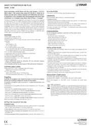
Produkspesifikasjoner
| Merke: | Lutron |
| Kategori: | Dimmer |
| Modell: | RMJS-8TN-DV-B |
Trenger du hjelp?
Hvis du trenger hjelp med Lutron RMJS-8TN-DV-B still et spørsmål nedenfor, og andre brukere vil svare deg
Dimmer Lutron Manualer
13 September 2025
Dimmer Manualer
Nyeste Dimmer Manualer
16 Oktober 2025

2 Oktober 2025
2 Oktober 2025
1 Oktober 2025
15 September 2025
12 September 2025
25 August 2025
25 August 2025
25 August 2025
25 August 2025