Panduit VS-AVT-C08-L10 Bruksanvisning

Panduit Ikke kategorisert VS-AVT-C08-L10

Les nedenfor 📖 manual på norsk for Panduit VS-AVT-C08-L10 (21 sider) i kategorien Ikke kategorisert. Denne guiden var nyttig for 3 personer og ble vurdert med 4.5 stjerner i gjennomsnitt av 2 brukere

Side 1/21
0BVeriSafe AVT
B21052
Rev: 15 2-2022
Absence of Voltage Tester
Instruction Manual
Models: VS-AVT-C02-L03, VS-AVT-C08-L10
© Panduit Corp. 2021
Original Instructions
TO REDUCE THE RISK OF INJURY, USER
MUST READ INSTRUCTION MANUAL
NOTE: In the interest of higher quality and value, Panduit products are
continually being improved and updated. Consequently, pictures may vary
from the enclosed product.
NOTE: Updates to this Instruction Manual may be available. Check
www.panduit.com for the latest version of this manual.
North America Tech Support:
techsupport@panduit.com
Tel: 1-866-405-6654
EU Tech Support :
techsupportemea
@panduit.com
Tel: +31-546-580-452
Fax: +31-546-580-441
www.panduit.com
Asia Pacific Tech Support:
TechSupportAP@ panduit.com
Telephone:
Singapore: 1-800-Panduit (7263848)
Australia: 1-800-Panduit (7263848)
Korea: 02-21827300
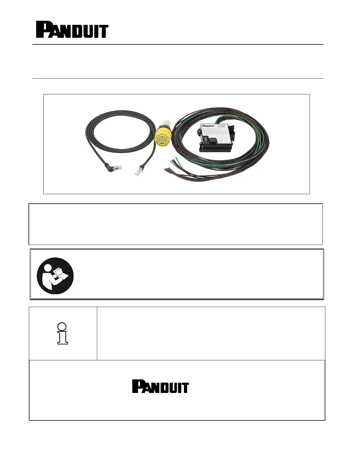
The VeriSafe Absence of Voltage Tester is a permanently-mounted tester that is used to verify a circuit is
de-energized prior to opening an electrical enclosure. Once installed, a push of a button enables personnel who
have been trained on the operation of the tester to verify the absence of voltage and see an active indication
when the absence of voltage is confirmed. The Indicator Module is designed for a 30-mm notched panel knockout
and the Isolation Module can be mounted to DIN rail or surface mounted using screws.
© Panduit Corp. 2021
INSTRUCTION MANUAL
VeriSafe AVT
B21052_15 Page: 1 of 20 2-2022
Table of Contents
Safety Information ............................................................................................................................ 2
Information de Sécurité ..................................................................................................................... 3
Components ..................................................................................................................................... 4
Output Contacts ................................................................................................................................ 4
Technical Specifications ................................................................................................................... 5
Dimensions ....................................................................................................................................... 7
Schematics ....................................................................................................................................... 8
Installation Considerations .............................................................................................................. 11
Installation Instructions ................................................................................................................... 13
Commissioning Checklist: ............................................................................................................... 15
Operating Instructions ..................................................................................................................... 16
Troubleshooting .............................................................................................................................. 17
Maintenance ................................................................................................................................... 18
Battery Replacement ................................. 18
AVT System Cable Removal ..................... 19
O-ring Replacement .................................. 19
Cleaning Instructions ................................. 19
Visual Inspection ....................................... 19
Warranty ......................................................................................................................................... 20
© Panduit Corp. 2021
INSTRUCTION MANUAL
VeriSafe AVT
B21052_15 Page: 2 of 20 2-2022
Safety Information
This manual contains information and warnings which must be followed to ensure safe operation of the AVT. If the AVT is not used
as described in this manual, the safety features of the AVT might be impaired. Failure to comply with the warnings and
information in this manual could result in product failure, electrical shock, severe injury or death.
Warning:
Always de-energize power before accessing an electrical enclosure.
Always follow safety and lockout/tagout procedures when working on or near electrical systems and equipment.
Use of the AVT does not replace lockout/tagout procedures. The AVT is intended to be used in conjunction with lockout/tagout processes
and only addresses the absence of voltage verification step.
Use proper personal protective equipment (PPE) when working around sources of hazardous electrical energy.
Do not use this product outside of the specified performance and environmental limits.
This product must be installed by a qualified electrical worker familiar with local and national electrical codes.
The AVT will only test for absence of voltage at the point in the circuit where it is installed. If there are other sources of power in the
equipment, dangerous voltage may be present.
Lack of red voltage presence indicators alone does not verify the absence of voltage, the Absence of Voltage test must be initiated
followed by the illumination only of the green indicator to verify the absence of voltage.
The AVT must be installed correctly and grounded as described in this Instruction Manual to provide proper indication of absence of
voltage. Sensor leads must not be mechanically connected with each other for the device to verify connection to the circuit. Correct
function of the device must be verified after installation (see commissioning checklist).
Sensor leads of the same label designation should be terminated on the same conductor (L1, L2, L3, GND). Each conductor should have
at least one sensor lead set, as shown on the schematic diagrams.
Excess length from Sensor Leads should be trimmed; Sensor Leads should not be extended with a splice.
Always comply with local installation codes and standards.
The product uses a lithium battery that is a fire, explosion and severe burn hazard. Do not crush, recharge, disassemble or heat above
85
C, incinerate, or expose contents to water.
Use only the included AVT System Cable or approved replacement cables to connect the Isolation Module and Indicator Module. Do not
use a standard Ethernet cable.
Battery, AVT System Cable and O-rings can be replaced. No other part of the product is serviceable. Do not attempt to open the Indicator
Module or Isolation Module for repair or modification. When servicing this product, only use specified replacement parts.
The section of the Indicator Module that is external to the electrical enclosure is approved for wash down when installed in an
appropriate enclosure. Before a wash down operation, ensure the o-rings are in good condition, the faceplate is undamaged and fully
secured to the unit and the cap is fully installed.
The AVT System Cable must be separated from the sensor leads and other circuits in the electrical enclosure by a minimum of 0.25
inches (6 mm).
To prevent damage to the AVT in high-vibration installations, surface mount the Isolation Module using screws and secure the Sensor
Lead Wires and AVT System Cable to prevent strain on the connection points.
If a Sensor Lead separates from the termination point to the power conductor and contacts a low impedance path to ground, the
connectivity test can be defeated resulting in a false absence of voltage indication. Ensure all sensor leads are terminated properly and
secured to the power conductor or other nearby rigid feature to prevent movement if the termination fails to remain intact.
The VeriSafe AVT is designed for use in 50/60Hz electrical systems. The AVT should not be installed on sections of a circuit where the
AVT is exposed to high frequency energy such as variable frequency drives (VFD) or other circuit elements generating high frequency
energy (waveforms exhibiting high Electro-Magnetic Interference (EMI) AC or variable frequency AC power). For more information on
where to position the VeriSafe AVT in VFD applications, see the Technical Note available on Panduit.com.
Should a problem occur during installation, operation or maintenance of the VeriSafe AVT, contact Panduit using one of the technical
support or customer service numbers listed on the cover of this manual. Contact Panduit if you have any product problems related to the
safety function of the product. The product model number and serial number are printed on the Isolation Module and Indicator Module
labels.
VeriSafe is a product containing electronic circuit boards in both the Indicator and Isolation Modules. The Indicator Module
contains a lithium battery. When decommissioning, remove the battery. Do not discard the battery in the trash; take it to an
appropriate battery recycling facility. The Indicator and Isolation Modules can be disposed of at an electronics recycling facility.

Produkspesifikasjoner

Merke: Panduit
Kategori: Ikke kategorisert
Modell: VS-AVT-C08-L10

Trenger du hjelp?

Hvis du trenger hjelp med Panduit VS-AVT-C08-L10 still et spørsmål nedenfor, og andre brukere vil svare deg


Ikke kategorisert Panduit Manualer

Ikke kategorisert Manualer

Nyeste Ikke kategorisert Manualer