Siemens 6EP1334-7CA00 Bruksanvisning
Siemens
Ikke kategorisert
6EP1334-7CA00
Les nedenfor 📖 manual på norsk for Siemens 6EP1334-7CA00 (4 sider) i kategorien Ikke kategorisert. Denne guiden var nyttig for 27 personer og ble vurdert med 4.8 stjerner i gjennomsnitt av 14 brukere
Side 1/4

© 3 Siemens, All rights reserved Ⓟ
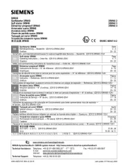
PSU100P 01 .201- -6419, 06 4
SITOP PSU100
SITOP PSU100
SITOP PSU100
SITOP PSU100SITOP PSU100P
P
P
P P
6EP1333-
6EP1333-
6EP1333-
6EP1333-6EP1333-
7CA00 24 V / 5 A
7CA00 24 V / 5 A
7CA00 24 V / 5 A
7CA00 24 V / 5 A7CA00 24 V / 5 A
6EP1334-
6EP1334-
6EP1334-
6EP1334-6EP1334-7CA00 24 V / 8 A
7CA00 24 V / 8 A
7CA00 24 V / 8 A
7CA00 24 V / 8 A 7CA00 24 V / 8 A
Betriebs
Betriebs
Betriebs
BetriebsBetriebsanleitung (kompakt)
anleitung (kompakt)
anleitung (kompakt)
anleitung (kompakt)anleitung (kompakt)
Operating Inst
Operating Inst
Operating Inst
Operating InstOperating Instructions (compact)
ructions (compact)
ructions (compact)
ructions (compact)ructions (compact)
Notice de servic
Notice de servic
Notice de servic
Notice de servicNotice de service (compacte)
e (compacte)
e (compacte)
e (compacte)e (compacte)
Istruzi
Istruzi
Istruzi
IstruziIstruzioni operative (descrizione sintet
oni operative (descrizione sintet
oni operative (descrizione sintet
oni operative (descrizione sintetoni operative (descrizione sintetica)
ica)
ica)
ica)ica)
Instrucc
Instrucc
Instrucc
InstruccInstrucciones de servicio (resumidas)
iones de servicio (resumidas)
iones de servicio (resumidas)
iones de servicio (resumidas)iones de servicio (resumidas)
Bild 1: Ansicht Geräte
Figure 1: View of units
Figure 1: Vue des appareils
Figura 1: Vista degli apparecchi
Figura 1: Vista de aparatos
B ild 2: Maßbild
Figure 2: Dimensions
Figure 2: Dimensions
Figura 2: Dimensione
Figura 2: plano acotado
ENGLISH
ENGLISH
ENGLISH
ENGLISH ENGLISH
Descri
Descri
Descri
DescriDescription
ption
ption
ptionption
The PSU100P SITOP power supplies
are provided for Indoor and Outdoor
application, degree of protection IP67,
protection class I.
Primary switched-mode power supplies
for connection to 1-phase AC system
(TN, TT system in accordance with
VDE -0100 T 300 / IEC 364 3) with rated
voltages of 120/230 V, 50/60 Hz;
+24 V DC output voltage, isolated,
short-circuit-proof and idling-proof.
See also Figure 1
Safety not
Safety not
Safety not
Safety notSafety notes
es
es
eses
NOTIC
NOTIC
NOTIC
NOTICNOTICE
E
E
EE
Appropriate transport, proper storage,
mounting, and installation, as well as
careful operation and service, are
essential for the error-free, safe and
reliable operation of the device/system.
Setup and operation of this
device/system are permitted only if the
instructions and warnings of the
corresponding documentation are
observed.
Only qualified personnel are allowed to
install the device/system and set it into
operation.
Assembli
Assembli
Assembli
AssembliAssembling
ng
ng
ngng
Wall mounting.
The device must be mounted in such a
way that the input and output terminals
are at the bottom.
A clearance of at least 50 mm must be
maintained above and 20mm in front of
the device .
See Figurealso 2
See Figure also 4
Bild 3: Input
① ② Output , Meldekontakt ③
Figure 3: Input
① ② Output , signaling contact ③
Figure 3: Input
① ②Output , contact de signalisation ③
Figura 3: Input
① ② Output , contatto di segnalazione ③
Figura 3: Entradas
①Salidas ②, contacto de
señalización
③
Bild 4:
⑤ Freiraum für Kühlung
Figure 4:
⑤ Required clearance for cooling
Figure 4:
⑤ Espace libre pour refroidissement
Figura 4:
⑤ Spazio libero per raffreddamento
Figura 4:
⑤ Espacio libre para refrigeración
Connecti
Connecti
Connecti
ConnectiConnecting
ng
ng
ngng
WARNING
WARNING
WARNING
WARNINGWARNING
Before installation or maintenance work
can begin, the system's main switch
must be switched off and measures
taken to prevent it being switched on
again. If this instruction is not observed,
touching live parts can result in death or
serious injury. It is only permissible to
use an insulated screwdriver when
actuating the potentiometer. For
installation of the devices, the relevant
country-specific regulations must be
observed.
The supply voltage (1 AC 120/230 V)
must be connected in accordance with
IEC 60364 and EN 50178.
Instructio
Instructio
Instructio
InstructioInstructions for UL c
ns for UL c
ns for UL c
ns for UL cns for UL compliant
ompliant
ompliant
ompliantompliant use:
use:
use:
use: use:
The input/output connection is to be
made using UL-Listed (CYJV)
connector/cable combination with
minimum ratings of 300 V, 8 A, 60°C
operating temperature.
The signal connection is to be made
using UL-Listed (CYJV) connector/cable
combination with minimum ratings of
240 V, 4 A, 60°C operating
temperature.
Plug connector
Plug connector
Plug connector
Plug connectorPlug connectors
s
s
s s
are not
are not
are not
are not are not inc
inc
inc
incincluded
luded
luded
ludedluded
Input ①:
cable connector 7/8"-16UN 3 Pol.
E. Binder - - - g. 99 2440 12 03
Output ②:
cable connector 7/8"- -Pol UN 4
E. Binder - - - g. 99 2443 12 04
Signaling Contact ③:
cable connector M12, 4- Pol
E. Binder - - - g. 99 0429 14 04
See also Figure 3
Struct
Struct
Struct
StructStructure
ure
ure
ureure
①
AC input
②
DC output
③
Signaling contact
④
Indicator light (24 V OK)
⑤
Clearance for cooling
④
① ③ ②
⑤
20
Produkspesifikasjoner
| Merke: | Siemens |
| Kategori: | Ikke kategorisert |
| Modell: | 6EP1334-7CA00 |
Trenger du hjelp?
Hvis du trenger hjelp med Siemens 6EP1334-7CA00 still et spørsmål nedenfor, og andre brukere vil svare deg
Ikke kategorisert Siemens Manualer
29 August 2025

2 Januar 2025

2 Januar 2025

2 Januar 2025

10 Desember 2024

16 Oktober 2024

16 Oktober 2024

16 Oktober 2024

16 Oktober 2024
Ikke kategorisert Manualer
- Blue Evolution
- Medel
- Volcano
- Nivona
- Duravit
- Nintendo
- Edouard Rousseau
- Bright Starts
- EAT
- Elmo
- Icy Dock
- Shure
- NeoMounts
- Zaahn
- Memphis Audio
Nyeste Ikke kategorisert Manualer

23 Oktober 2025

23 Oktober 2025

23 Oktober 2025

23 Oktober 2025

23 Oktober 2025

23 Oktober 2025

23 Oktober 2025

23 Oktober 2025

23 Oktober 2025

23 Oktober 2025