Stiebel Eltron ISG Connect Bruksanvisning
Stiebel Eltron
Ikke kategorisert
ISG Connect
Les nedenfor 📖 manual på norsk for Stiebel Eltron ISG Connect (16 sider) i kategorien Ikke kategorisert. Denne guiden var nyttig for 15 personer og ble vurdert med 4.3 stjerner i gjennomsnitt av 8 brukere
Side 1/16
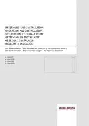
SCHNELLEINSTIEG
ISG Connect
www.stiebel-eltron.com ISG Connect | 1
DEUTSCH
DEUTSCH
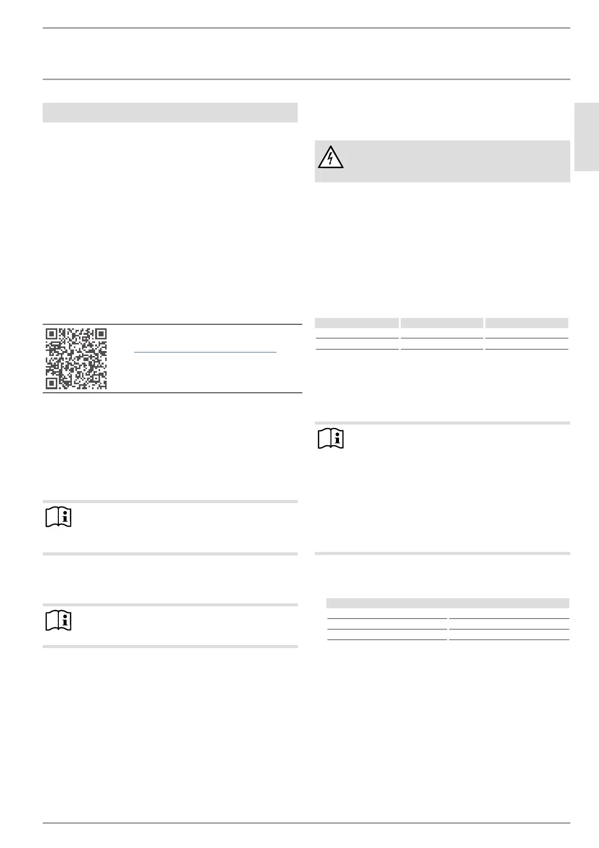
1. Lieferumfang
- 1 x Netzteil
- 1 x Wandhalterung
- 1 x CAN-Bus-Kabel (Länge 3,0 m)
- 1 x Netzwerk-/Patchkabel (Länge 3,0 m)
- 1 x Steuerleitung (schwarz, Länge 3,0 m) mit
Anschlussstecker
2. Systemvoraussetzungen
Wärmeerzeuger
Das Herstelldatum des Wärmeerzeugers (Wärmepumpe/ Lüf-
tungsintegralgerät) sowie der Softwarestand Ihres Reglers sind
entscheidend für die Kompatibilität mit dem ISG Connect.
Kompatibilitätsliste ISG
f Herunterladen von stiebel-eltron.de
Computer
- Netzwerkanschluss (Standard-Ethernet 10/100 Base-T)
- Breitband-Internetzugang und aktuellen Internet-Browser
Router
- DHCP aktiv
- freie Ethernet-Schnittstelle
Hinweis
Deaktivieren Sie die Energiesparfunktion des für das
ISGConnect gewählten Ethernet-Ports Ihres Routers,
sofern diese aktiviert ist.
Relais (SG ready)
- 1 bis 2 potenzialfreie Relais-Ausgänge (Schließer)
Hinweis
1 Relais-Ausgang ≘ 2 SGReady-Zustände
2 Relais-Ausgänge ≘ 4 SGReady-Zustände
3. Bei SG Ready: Steuerleitung anschließen
Nur bei SG-Ready-Nutzung erforderlich:
WARNUNG Stromschlag
Geben Sie keine Spannung auf die Kontakte der Steu-
erleitung.
f Schließen Sie die Steuerleitung über die Buchse „SG READY“
an das Gerät an.
Die Litzen der Steuerleitung sind folgendermaßen belegt:
- Weiß = Eingang 1 / SG Ready-Kontakt 1
- Braun = Eingang 2 / SG Ready-Kontakt 2
- Grün = nicht belegt
- Gelb = Gemeinsame Masse für getrennte Eingänge SG1, SG2
f Je nachdem, welche SG-Ready-Funktionen Sie nutzen möch-
ten, beschalten Sie die Kontakteingänge der Steuerleitung.
Funktion SGReady Kontakt 1 SGReady Kontakt 2
SGReady x x
PV-Optimierung x -
f Isolieren Sie die rote Litze der Steuerleitung.
4. Netzwerk, CAN-Bus und Netzteil
anschließen
Hinweis
- Schließen Sie das ISG Connect nach beendeter Inbe-
triebnahme aller Busteilnehmer als letztes Gerät an
den CAN-Bus an
- Das ISG Connect wird an die Schnittstelle für die
zweite Bedieneinheit oder die Fernbedienung Ihrer
Wärmepumpe/ Ihres Lüftungsintegralgeräts ange-
schlossen.
- Bei nur einer vorhandenen Schnittstelle wird das
ISG Connect wie eine weitere Bedieneinheit parallel
auf den CAN-Bus aufgelegt.
f Verbinden Sie das ISG Connect mit dem beiliegenden CAN-
Bus-Kabel über eine der beiden COM-Schnittstellen mit Ihrer
Anlage.
Belegung des CAN-Bus-Kabels
Weiß High
Blau Low
Grün Masse (Ground)
f Schließen Sie das ISG Connect über die Buchse „LAN“ mit
dem mitgelieferten Patchkabel an Ihren Router an.
f Stellen Sie sicher, dass der WPM in Betrieb genommen
wurde und vollständig gestartet ist.
f Schließen Sie das ISG Connect mit dem mitgelieferten USB-C-
Netzteil an das Stromnetz an.
Nach Anschluss des Netzsteckers schaltet das ISG Connect ein und
wird vom WPM initialisiert. Dauer je nach Wärmepumpentyp 5 bis
10 Minuten (Kaskade). Währenddessen blinkt die LED 1 (links).
Produkspesifikasjoner
| Merke: | Stiebel Eltron |
| Kategori: | Ikke kategorisert |
| Modell: | ISG Connect |
Trenger du hjelp?
Hvis du trenger hjelp med Stiebel Eltron ISG Connect still et spørsmål nedenfor, og andre brukere vil svare deg
Ikke kategorisert Stiebel Eltron Manualer
23 August 2025

23 August 2025
11 August 2025
11 August 2025
11 August 2025
11 August 2025
11 August 2025
11 August 2025

22 Mars 2025

22 Mars 2025
Ikke kategorisert Manualer
- Hypnos
- Ambient Weather
- OnePlus
- Racktime
- Celexon
- GoXtreme
- Sloan
- Karran
- Vankyo
- Senseca
- ISi
- Dexibell
- Kahayan
- Transparent
- Constructa
Nyeste Ikke kategorisert Manualer

23 Oktober 2025

23 Oktober 2025

23 Oktober 2025

23 Oktober 2025

23 Oktober 2025

23 Oktober 2025

23 Oktober 2025

23 Oktober 2025

23 Oktober 2025

23 Oktober 2025