Wesco 272460 Bruksanvisning
Wesco
Ikke kategorisert
272460
Les nedenfor 📖 manual på norsk for Wesco 272460 (26 sider) i kategorien Ikke kategorisert. Denne guiden var nyttig for 17 personer og ble vurdert med 4.6 stjerner i gjennomsnitt av 9 brukere
Side 1/26
Page1of26
©Copyright 2018 WESCO Industrial Products, LLC. Specifications subject to change. Not responsible for errors or omissions.
TABLE OF CONTENTS
1 General Information ........................................................................................................................... 2
1.1 Description.............................................................................................................................. 2
1.2 Specifications.......................................................................................................................... 2
2 Safety Information................................................................................................................................ 2
3 Assembly.....……….............................................................................................................................. 2
4 Hydraulic Valve Adjustment................................................................................................................. 2
5 Operation.............................................................................................................................................. 4
6 Battery Charging & Replacement......................................................................................................... 5
7 Maintenance......................................................................................................................................... 7
8 Trouble Shooting.................................................................................................................................. 8
9 Hydraulic & Circuit Diagrams............................................................................................................... 9
9.1 Hydraulic Flow Diagram (Models Manufactured Before 2010)................................................ 9
9.2 Circuit Diagram (Models Manufactured Before 2010).............................................................. 9
9.3 Hydraulic Flow Diagram (Models Manufactured Between 2010 & 2015)................................. 10
9.4 Circuit Diagram (Models Manufactured Between 2010 & 2015).............................................. 10
9.5 Hydraulic Flow Diagram (Models Manufactured After 2015)................................................... 11
9.5 Circuit Diagram (Models Manufactured After 2015)................................................................. 11
10 Part Information (Models Manufactured Before 2010)......................................................................... 12
10.1 Handle Part Diagram................................................................................................................ 12
10.2 Handle Part List........................................................................................................................ 12
10.3 Frame Part Diagram................................................................................................................. 13
10.4 Frame Part List......................................................................................................................... 13
10.5 Pump Part Diagram.................................................................................................................. 14
10.6 Pump Part List.......................................................................................................................... 14
10.7 Steer Wheel Assembly Part Diagram....................................................................................... 15
10.8 Steer Wheel Assembly Part List............................................................................................... 16
10 Part Information (Models Manufactured Between 2010 & 2015)......................................................... 17
10.1 Frame & Handle Part Diagram................................................................................................. 17
10.2 Frame & Handle Part List......................................................................................................... 18
10.3 Pump Part Diagram.................................................................................................................. 19
10.4 Pump Part List.......................................................................................................................... 20
11 Part Information (Models Manufactured After 2015)............................................................................ 21
11.1 Handle Part Diagram................................................................................................................ 21
11.2 Handle Part List........................................................................................................................ 21
11.3 Frame Part Diagram................................................................................................................. 22
11.4 Frame Part List......................................................................................................................... 22
11.5 Pump Part Diagram.................................................................................................................. 23
11.6 Pump Part List.......................................................................................................................... 24
11.7 External Charger Part Diagram................................................................................................ 25
11.8 External Charger Part List........................................................................................................ 26
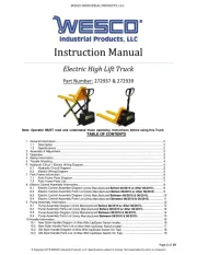
WESCOINDUSTRIALPRODUCTS,LLC
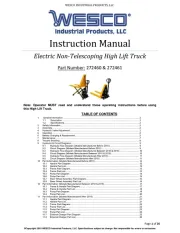
InstructionManual
ElectricNon‐TelescopingHighLiftTruck
PartNumber: 272460&272461
Note: Operator MUST read and understand these operating instructions before using
this High Lift Truck.
Produkspesifikasjoner
| Merke: | Wesco |
| Kategori: | Ikke kategorisert |
| Modell: | 272460 |
Trenger du hjelp?
Hvis du trenger hjelp med Wesco 272460 still et spørsmål nedenfor, og andre brukere vil svare deg
Ikke kategorisert Wesco Manualer
21 September 2025

21 September 2025
21 September 2025
21 September 2025

21 September 2025
21 September 2025

21 September 2025
21 September 2025
21 September 2025

20 September 2025
Ikke kategorisert Manualer
- C2G
- DPM
- Grundfos
- Stairville
- ESX
- Vogue
- JK Audio
- Singer
- Broan
- APSystems
- Total
- HomeCraft
- Proficare
- Velbus
- Cubot
Nyeste Ikke kategorisert Manualer

23 Oktober 2025

23 Oktober 2025

23 Oktober 2025

23 Oktober 2025

23 Oktober 2025

23 Oktober 2025

23 Oktober 2025

23 Oktober 2025

23 Oktober 2025

23 Oktober 2025