Yamaha VXC2FW Bruksanvisning
Les nedenfor 📖 manual på norsk for Yamaha VXC2FW (2 sider) i kategorien Høyttaler. Denne guiden var nyttig for 31 personer og ble vurdert med 4.9 stjerner i gjennomsnitt av 16 brukere
Side 1/2
1
PRECAUTIONS
PLEASE READ CAREFULLY BEFORE PROCEEDING
Please keep this manual in a safe place for future reference.
This product is a speaker system designed for background music and public address
applications in places such as stores, restaurants and other commercial spaces. Do not
use for any purposes other than the one intended. Those who are unfamiliar with handling
or those who can not handle according to this manual such as children, should be
supervised by responsible persons to ensure safety.
Always consult a professional installer if the product installation requires construction work.
WARNING
Always follow the basic precautions listed
below to avoid the possibility of serious
injury or even death from electrical shock,
short-circuiting, damages, fire or other
hazards. These precautions include, but
are not limited to, the following:
If you notice any abnormality
• If any of the following problems occur,
immediately turn off the power of the amplifier.
- Unusual smells or smoke are emitted.
- Some object, or water has been dropped
into the product.
- There is a sudden loss of sound during use
of the product.
- Cracks or other visible damage appear on
the product.
Then have the product inspected or repaired
by qualified Yamaha service personnel.
Do not open
• This product contains no user-serviceable
parts. Do not attempt to disassemble the
internal parts or modify them in any way.
Water warning/Fire warning
• Do not expose the product to rain, use it near
water or in damp or wet conditions, or place on
it any containers (such as vases, bottles or
glasses) containing liquids which might spill
into any openings.
• Do not place any burning items or open flames
near the product, since they may cause a fire.
Hearing loss
• When turning on the AC power in your audio
system, always turn on the power amplifier
LAST, to avoid hearing loss and speaker
damage. When turning the power off, the
power amplifier should be turned off FIRST for
the same reason.
CAUTION
Always follow the basic precautions listed
below to avoid the possibility of physical
injury to you or others. These precautions
include, but are not limited to, the
following:
Location and connection
• Do not place the product in an unstable
position or a location with excessive vibration,
where it might accidentally fall down and cause
injury.
• Keep this product out of reach of children, to
keep them from putting their fingers into
openings on the product and accidentally being
injured. This product is not suitable for use in
locations where children are likely to be present.
• Do not place the product in a location where it
may come into contact with corrosive gases or
salt air. Doing so may result in malfunction.
• Do not place the product in a location where it
may be exposed to smoke or oil vapors, or
where any of its parts might deteriorate and
cause malfunction.
• Before moving the product, remove all
connected cables.
• Do not use the speaker’s carrying band for
suspended installation. Doing so can result in
damage or injury.
• Always consult a professional installer if the
product installation requires construction work,
and make sure to observe the following
precautions.
- Choose mounting hardware and an
installation location that can support the
weight of the product.
- Avoid locations that are exposed to constant
vibration.
- Use the required tools to install the product.
- Inspect the product periodically.
• Use only speaker cables for connecting
speakers to the speaker jacks. Use of other
types of cables may result in fire.
Handling caution
• Do not insert your fingers or hands in any gaps
or openings on the product (bass reflex port,
clamps).
• Do not rest your weight on the product or place
heavy objects on it.
• When using a low-impedance connection,
make sure that the output power of the
amplifier is lower than the power capacity of
this product. When using a high-impedance
connection, be sure that the total rating of the
transformer taps of the speakers does not
exceed the output power of the amplifier. If the
output power is higher than the power
capacity, malfunction or fire may occur.
• Do not input excessively loud signals that may
result in clipping in the amplifier or cause the
following:
- Feedback, when using a microphone
- Continuous and extremely loud sound from a
musical instrument, etc.
- Continuous and excessively loud distorted
sound
- Noise caused by plugging/unplugging the
cable while the amplifier is turned on
Even if the output power of the amplifier is
lower than the power capacity of this product
(program), damage to the product,
malfunction or fire may occur.
PA_en_11
General Specifications
Unpacking
Unpack the contents and confirm that all the
following items are included.
• Speaker × 1
• Grille × 1
• Safety wire × 1
• Cutout template × 1
• Owner’s Manual (this manual)
* Speaker cable is not included.
Optional Items (sold separately)
Reinforcing Bracket Kit (AB-C2)
Bundled Items
• Tile rails × 2
• C-ring × 1
• Screws (S-TITE M4, 8 mm) × 2
* In this manual, we also explain the
installation method using the AB-C2
Reinforcing Bracket Kit.
Pendant Mount Kit (PK-C4B, PK-C4W)
The speaker can also be hung
from the ceiling using the PK-C4B
or PK-C4W Pendant Mount Kit.
For the installation method of the
speaker using the PK-C4B or PK-
C4W Pendant Mount Kit, refer to
the installation instructions
included in the kit.
*1 Half-space (2π)
*2 Calculated based on power rating and sensitivity, exclusive of power compression.
The contents of this manual apply to the latest specifications as of the
publishing date. To obtain the latest manual, access the Yamaha website then
download the manual file.
The dimensions are shown in “Dimensions” on the back side of the manual.
Type Full range, Bass reflex
Component 2.5" (6.4 cm) full range unit
Coverage angle 160° conical
Nominal impedance 8Ω
Power rating NOISE 15 W
PGM 30 W
MAX 60 W
Sensitivity (1 W, 1 m)
*1
86 dB SPL
Maximum SPL
(Calculated, 1m, Peak)
*2
104 dB SPL
Frequency range (-10 dB)
*1
67 Hz–20 kHz
Connector Euroblock (4-pin) × 1
(input: +/-, loop-thru: +/-)
Min. wire size AWG24 (0.2 sq)
Max. wire size AWG12 (3.5 sq)
Transformer
taps
100 V 1.9 W, 3.8 W, 7.5 W, 15 W
70 V 1 W, 1.9 W, 3.8 W, 7.5 W, 15 W
Overload protection Full-range power limiting, to protect network
and transducers
Magnetically shielded No
Enclosure Shape Round
Cabinet
material
Steel 1 mm, black
Baffle
material
ABS V-0, 5 mm, black
Grille Material Metal grille: Powder coated perforated steel
0.6 mm
Trim Ring: ABS V-0
Aperture ratio: 51%
Finish VXC2FB: Black paint
(approximate value: Munsell N3.0)
VXC2FW: White paint
(approximate value: Munsell N9.3)
Dimensions
(Including grille)
Ø225 × D89 mm
Net Weight (Including grille) 1.7 kg
Cutout size Ø186 mm
Required ceiling board
thickness
5 mm–37 mm
Conduit tube Ø15.4 mm–Ø21.3 mm
Packaging Single-unit (1 pc.)
Material and weight of the Reinforcing Bracket Kit (AB-C2): steel, 1.0 kg
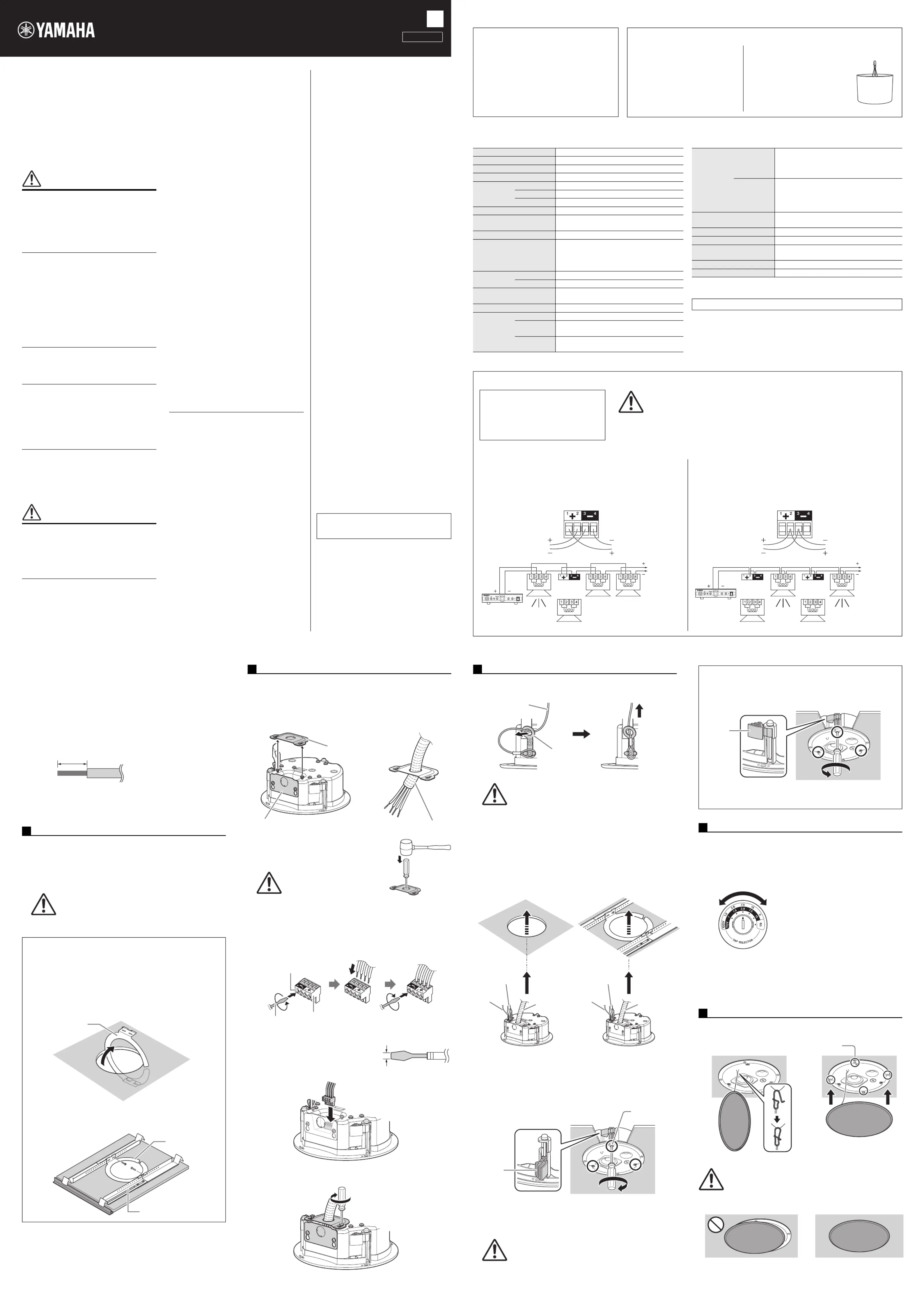
Connecting the Cable
Wiring and installation shall be in
accordance with the National Electrical
Code, NFPA70 for United States,
Canadian Electrical Code, CSA C22.1 for
Canada and the local authority having
jurisdiction.
Using Loop-Through Terminals
For this method, cables are connected from terminals 1 and 4 to the
subsequent speaker. Cables with a thickness of at least AWG24 (0.2 sq)
and up to AWG12 (3.5 sq) can be used. If the Euroblock plug is
disconnected from a speaker, all subsequent speakers will not work. This
can be useful to identify which speaker has a problem.
Paralleling Input Terminals
For this method, cables are connected to terminals 2 and 3 of each
speaker. Connect two cables to one terminal. Cables with a thickness up
to AWG17 can be used. Since the cables are connected via Euroblock
plugs, subsequent speakers can work properly.
From amplifier or
previous speakers
To subsequent
speakers
Power
amplifier
Speaker
To
subsequent
speakers
Euroblock
plug
From amplifier or
previous speakers
To subsequent
speakers
Power
amplifier
Speaker
To
subsequent
speakers
Euroblock
plug
CAUTION
• When connecting with low impedance, take note of the total impedance.
• When connecting speakers with high impedance, be sure that the total rated input capac-
ity of the speakers does not exceed the output power of the amplifier.
NOTICE
When using a high-impedance speaker connection, make sure the audio signal is passed through an
60 Hz or above high-pass filter before being input to the speakers.
Installing the Speaker
Before installing the speaker onto the ceiling, ensure that the strength of the
ceiling rail is sufficient.
Pre-installation (Preparation of the Cable)
• For cables attached to the Euroblock plug, strip the insulation as shown
in the figure and connect them.
1. Put the supplied cutout template to the ceiling and draw a circle by
tracing it.
Make sure to use the cutout template so that hole is the correct
diameter.
If you use a circular cutter, set the diameter using the cutout template.
2. Cut the hole by tracing the circle.
1. Pull the wiring from the power amplifier through the cut hole of the
ceiling.
2. Loosen the screws of one of the two terminal covers according to the
wiring direction and remove the terminal cover.
Pass the cable through the terminal cover.
In this manual, the illustrations show the top terminal cover removed.
The terminal covers do not have a hole
through which the speaker cable passes.
Open a hole in the terminal cover (as shown)
to use.
3. Remove the Euroblock plug from the speaker. After loosening the
terminal screws of the Euroblock plug with a flat-blade screwdriver,
insert the cable into each terminal and tighten the screws. For the
connection, refer to section “Connecting the Cable.”
Make sure that cables cannot be pulled out.
Use a flat-blade screwdriver with a
blade less than 3 mm.
4. Plug the connected Euroblock plug into the socket in the speaker.
5. Tighten the screw and then attach the terminal cover.
NOTICE
When installing the speakers, turn off the power amplifier.
NOTE
Do not plate core wires by soldering if the cable uses stranded wire.
Doing so will cause the wire to break.
Cut Out a Hole in the Ceiling
CAUTION
Wear goggles to prevent chips or powder entering your eyes
while cutting the hole.
When the AB-C2 Reinforcing Bracket Kit (sold separately)
is used
1.
Insert the two tile rails through the cut hole and place them on the
ceiling surface within your reach. Adjust their length and be sure that
each of the tile rails are oriented as shown below.
2. Use the opening in the C-ring to slide one section of the C-Ring into
the cut hole, continuing to slide it around until the C-ring is
completely inside the ceiling.
3. Secure the C-ring and tile rails with the supplied two screws through
either slot of both C-ring brackets.
About 7 mm
Compatible cable:
Min. AWG24 (0.2 sq)
Max. AWG12 (3.5 sq)
1
C-ring
C-ring
Tile rail
Connect the Wiring to the Connector
CAUTION
Use an appropriate tool for open-
ing the hole. Otherwise, injury
may result if you attempt to open
the hole with your bare hands.
2
Terminal cover
Terminal cover
Speaker cable
Terminal screw
Loosen
Flat-blade
screwdriver
Euroblock plug
Tighten
Less than 3 mm
1. Attach the safety wire to the safety wire ring, and connect the wire to an
independent support point, such as a joist.
2. Push the speaker slowly up into the ceiling, taking care not to trap the
speaker cable, carrying band or safety wire.
3. While lifting up the speaker, turn the screwdriver clockwise to tighten the
attachment screw.
The first turn of the attachment screw opens the clamp. Further turns
move the clamp down the channel to pull the speaker up into the ceiling.
When the clamp is difficult to open, turning the screwdriver halfway
counterclockwise once will make it easier to open the clamp.
Select the line voltage/impedance (100 V, 70 V, 8Ω) and power tap for a
100 V, 70 V line distributed system, by rotating the tap selector switch on
the front side of the speaker with a flat-blade screwdriver.
When using the speaker with high-impedance connection, select the
position where wattage is indicated by the line (100 V, 70 V). Do not select
the “ × ” setting when connecting to a 100V line.
When using it with low impedance connection, select the 8Ω position.
Attach the string to the speaker as shown in the figure, and then fit the grille
to the magnets (4 places) on the baffle front.
Fix the Speaker onto the Ceiling
CAUTION
Always take measures to prevent the speaker from falling
down.
If the safety wire is too short, prepare another wire appropri-
ate for the speaker weight and installation conditions. If the
wire is too long, should the speaker fall, the wire may break
as a result of too much strain.
NOTICE
Do not over-tighten the attachment screws. Otherwise, the attachment
screws and clamps will break.
CAUTION
Do not turn any screws other than the attachment screws.
Otherwise, the speaker may fall or malfunction.
3
Safty wire
ring
Safety wire
Carrying band
Safety wire
Speaker
cable
Carrying band
Safety wire
Speaker
cable
When the AB-C2 Reinforcing
Bracket Kit (sold separately)
is used.
When the AB-C2 Reinforcing
Bracket Kit (sold separately)
is not used.
Attachment
screw
Clamp
Removing from the Ceiling
1.
Loosen the attachment screws by turning them counterclockwise.
Loosen the screw and the clamp goes up, and as it reaches the top,
the clamp closes as shown in figure below.
2. Remove the safety wire from the speaker that is detached from the
ceiling.
Set the Line Voltage/Impedance and Power
NOTICE
• Make sure the amplifier is switched off before operating the tap selector
switch.
• If the setting is incorrect, it may cause malfunction of the speaker and
amplifier.
Attach the Grille
CAUTION
The grille may fall down if it is attached inadequately. Attach it
firmly.
Clamp
4
The illustration indicates the setting at 7.5 W for
a 100 V line and 3.8 W for a 70 V line.
5
Magnet
Incorrectly attached Correctly attached
SPEAKER SYSTEM
VXC2FB VXC2FW
Owner’s Manual
EN
English
VCM7590
NOTICE
To avoid the possibility of malfunction/damage to
the product or other property, follow the notices
below.
Handling and maintenance
• Do not expose the product to excessive dust or
vibration, or extreme cold or heat, in order to
prevent the possibility of panel disfiguration,
unstable operation, or damage to the internal
components.
• When using a high-impedance speaker
connection, make sure the audio signal is
passed through an 60 Hz or above high-pass
filter before being input to the speakers.
• Do not touch the speaker driver unit, since it
might cause malfunction.
• Be sure to observe the amplifier’s rated load
impedance, particularly when connecting
speakers in parallel at low impedance.
Connecting an impedance load outside the
amplifier's rated range can damage the
amplifier.
• Do not place vinyl, plastic or rubber objects on
the product, since this might cause alteration
or discoloration of the panel.
• When cleaning the product, use a dry and soft
cloth. Do not use paint thinners, solvents,
cleaning fluids, or chemical-impregnated
wiping cloths, since this might cause alteration
or discoloration.
• Protection Circuit
This speaker system has an internal protection
circuit that shuts off the speaker unit when an
excessive input signal is applied. If the
speaker unit emits no sound, reduce the
volume level of the amplifier immediately. (The
sound will return automatically in several
seconds.)
• Do not place the speaker face down with the
grille attached, as deformation of the grille may
result.
• When placing the speaker face down, always
place it on a flat surface.
• Air blowing out of the bass reflex ports is
normal, and often occurs when the speaker is
handling program material with heavy bass
content.
Information
About this manual
• The illustrations as shown in this manual are for
instructional purposes only.
• The company names and product names in
this manual are the trademarks or registered
trademarks of their respective companies.
About disposal
• This product contains recyclable components.
When disposing of this product, please contact
the appropriate local authorities.
Yamaha cannot be held responsible for
damage caused by improper use or
modifications to the product.
Produkspesifikasjoner
| Merke: | Yamaha |
| Kategori: | Høyttaler |
| Modell: | VXC2FW |
Trenger du hjelp?
Hvis du trenger hjelp med Yamaha VXC2FW still et spørsmål nedenfor, og andre brukere vil svare deg
Høyttaler Yamaha Manualer

30 August 2025

29 August 2025

28 August 2025
28 August 2025

28 August 2025

28 August 2025

28 August 2025

28 August 2025

28 August 2025
28 August 2025
Høyttaler Manualer
- Antelope
- Sonance
- Memphis Audio
- Behringer
- Champion
- Transparent
- DAP Audio
- Power Dynamics
- Insignia
- Rockford Fosgate
- REL Acoustics
- Trevi
- Monster
- GMB Audio
- Fresh N Rebel
Nyeste Høyttaler Manualer

23 Oktober 2025

21 Oktober 2025
21 Oktober 2025

20 Oktober 2025
20 Oktober 2025

20 Oktober 2025
20 Oktober 2025
20 Oktober 2025

20 Oktober 2025
20 Oktober 2025