ZZ-2 ZW-GM Bruksanvisning
ZZ-2
Ikke kategorisert
ZW-GM
Les nedenfor 📖 manual på norsk for ZZ-2 ZW-GM (4 sider) i kategorien Ikke kategorisert. Denne guiden var nyttig for 16 personer og ble vurdert med 3.7 stjerner i gjennomsnitt av 8.5 brukere
Side 1/4
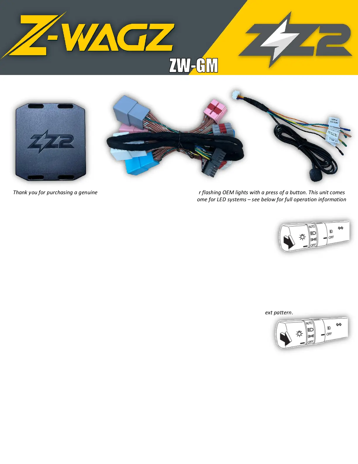
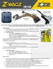
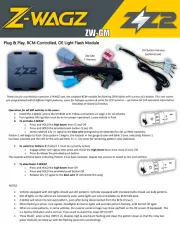
Plug & Play, BCM-Controlled, OE Light Flash Module
Thank you for purchasing a genuine Z-WAGZ unit, the simplest BCM-module for flashing OEM lights with a press of a button. This unit comes
pre-programmed with 8 different light patterns, some for halogen systems & some for LED systems – see below for full operation information
including on-board LED status.
Operation for all GM vehicles is the same:
1. Install the Z-WAGZ unit to the OE BCM unit. Follow instructions on page 2 for all vehicles.
2. Turn Ignition ON (Ignition must be on for proper operation). Leave vehicle in Park.
3. To activate Z-WAGZ:
o Press and HOLD the high beam lever (5 sec) OR
o Press and HOLD the provided push button (3 sec) OR
o Send a latched 12v (+) signal to the blue wire (designed to be extended for OE up-fitter switches)
Pattern 1 will begin to flash. Once pattern 1 begins, the hazards in the gauge cluster will blink 1 time, indicating Pattern 1
has been selected and the LED on the unit will blink BLUE. See chart for remaining pattern color indication.
4. To switch to Pattern 2: (Pattern 1 must be currently active)
o Engage either turn signal, then press and HOLD the high beam lever once more (5 sec). OR
o Press & release the provided push button
The hazards will blink twice indicating Pattern 2 has been selected. Repeat this process to switch to the next pattern.
5. To deactivate Z-WAGZ:
o Press and HOLD the high beam lever OR
o Press and HOLD the provided push button OR
o Release 12v (+) signal to the blue wire (if connected this way)
NOTES:
• Vehicles equipped with LED lights should use LED patterns. Vehicles equipped with standard bulbs should use bulb patterns.
• Not all lights on the vehicle are necessarily used, some lights are not controllable via BCM CAN data.
• Z-WAGZ will retain the last used pattern, even after being disconnected from the BCM (if ever).
• When flashing is active: turn signals, headlights & reverse lights will override pattern flashing, until turned off again.
• When on some patterns, in some vehicles, the reverse camera image may show up/flash on the OE screen (if equipped). This
is a factory limitation and is normal. If you want to avoid this, keep DIP (3) OFF.
• ‘Plow Mode’, when active (INPUT 2), disables High & Low beam flashing and slows the pattern down so that the relay box
(plow module) can keep up with the flashing (prevents overheating).
I/O Button Harness
(optional use)
ZW-GM
T-Harness
Produkspesifikasjoner
| Merke: | ZZ-2 |
| Kategori: | Ikke kategorisert |
| Modell: | ZW-GM |
Trenger du hjelp?
Hvis du trenger hjelp med ZZ-2 ZW-GM still et spørsmål nedenfor, og andre brukere vil svare deg
Ikke kategorisert ZZ-2 Manualer

7 September 2025
6 September 2025
6 September 2025

31 Januar 2025
Ikke kategorisert Manualer
- Techno Line
- Domo
- Mount-It!
- Kanlux
- United Office
- Tineco
- Brilliant
- Motorola
- Stairville
- Triplett
- N8WERK
- Hughes & Kettner
- Nethix
- Viomi
- Cylinda
Nyeste Ikke kategorisert Manualer

23 Oktober 2025

23 Oktober 2025

23 Oktober 2025

23 Oktober 2025

23 Oktober 2025

23 Oktober 2025

23 Oktober 2025

23 Oktober 2025

23 Oktober 2025

23 Oktober 2025