Carrier 42NQV035 Bruksanvisning
Carrier
luftkondisjonering
42NQV035
Les nedenfor 📖 manual på norsk for Carrier 42NQV035 (14 sider) i kategorien luftkondisjonering. Denne guiden var nyttig for 6 personer og ble vurdert med 4.8 stjerner i gjennomsnitt av 3.5 brukere
Side 1/14

• Never modify this unit by removing any of the safety guards or bypassing any of the safety interlock switches.
• Do not install in a place which cannot bear the weight of the unit.
Personal injury and property damage can result if the unit falls.
• Before doing the electrical work, attach an approved plug to the power supply cord.
Also, make sure the equipment is properly earthed.
• Appliance shall be installed in accordance with national wiring regulations.
If you detect any damage, do not install the unit. Contact your Carrier dealer immediately.
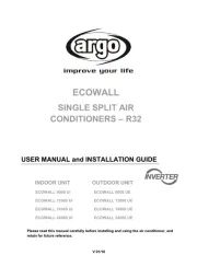
AIR CONDITIONER (SPLIT TYPE)
42NQV025, 035, 045 Series
Indoor Unit
INSTALLATION MANUALINSTALLATION MANUAL
38NYV025, 035, 045 Series
Outdoor Unit
PRECAUTIONS FOR SAFETYPRECAUTIONS FOR SAFETY
For general public use
Power supply cord of parts of appliance for outdoor use shall be at least polychloroprene sheathed fl exible cord (design
H07RN-F) or cord designation 245 IEC66 (1.5 mm
2
or more). (Shall be installed in accordance with national wiring
regulations.)
• THIS AIR CONDITIONER USES THE NEW HFC REFRIGERANT (R410A), WHICH DOES NOT DESTROY THE
OZONE LAYER.
R410A refrigerant is apt to be affected by impurities such as water, oxidizing membranes, and oils because the pressure
of R410A refrigerant is approx. 1.6 times of refrigerant R22. As well as the adoption of this new refrigerant, refrigerating
machine oil has also been changed. Therefore, during installation work, be sure that water, dust, former refrigerant, or
refrigerating machine oil does not enter the refrigeration cycle of a new-refrigerant air conditioner.
To avoid mixing refrigerant and refrigerating machine oil, the sizes of charging port connecting sections on the main unit
are different from those for the conventional refrigerant, and different size tools are also required. For connecting pipes,
use new and clean piping materials with highpressure withstand capabilities, designed for R410A only, and ensure that
water or dust does not enter. Moreover, do not use any existing piping as its pressure withstand may be insuffi cient and
may contain impurities.
• FOR USE BY QUALIFIED PERSONS ONLY.
• TURN OFF MAIN POWER SUPPLY BEFORE ATTEMPTING ANY ELECTRICAL WORK. MAKE SURE ALL POWER
SWITCHES ARE OFF.
FAILURE TO DO SO MAY CAUSE ELECTRIC SHOCK.
• CONNECT THE CONNECTING CABLE CORRECTLY. IF THE CONNECTING CABLE IS CONNECTED WRONGLY,
ELECTRIC PARTS MAY BE DAMAGED.
• CHECK THE EARTH WIRE THAT IT IS NOT BROKEN OR DISCONNECTED BEFORE INSTALLATION.
• DO NOT INSTALL NEAR CONCENTRATIONS OF COMBUSTIBLE GAS OR GAS VAPORS.
FAILURE TO FOLLOW THIS INSTRUCTION CAN RESULT IN FIRE OR EXPLOSION.
• TO PREVENT OVERHEATING THE INDOOR UNIT AND CAUSING A FIRE HAZARD, PLACE THE UNIT WELL AWAY
(MORE THAN 2 M) FROM HEAT SOURCES SUCH AS RADIATORS, HEATERS, FURNACE, STOVES, ETC.
• WHEN MOVING THE AIR CONDITIONER FOR INSTALLING IT IN ANOTHER PLACE AGAIN, BE VERY CAREFUL NOT
TO GET THE SPECIFIED REFRIGERANT (R410A) WITH ANY OTHER GASEOUS BODY INTO THE REFRIGERATION
CYCLE. IF AIR OR ANY OTHER GAS IS MIXED IN THE REFRIGERANT, THE GAS PRESSURE IN THE REFRIGERATION
CYCLE BECOMES ABNORMALLY HIGH AND IT RESULTINGLY CAUSES BURST OF THE PIPE AND INJURIES ON
PERSONS.
• IN THE EVENT THAT THE REFRIGERANT GAS LEAKS OUT OF THE PIPE DURING THE INSTALLATION WORK,
IMMEDIATELY LET FRESH AIR INTO THE ROOM. IF THE REFRIGERANT GAS IS HEATED BY FIRE OR SOMETHING
ELSE, IT CAUSES GENERATION OF POISONOUS GAS.
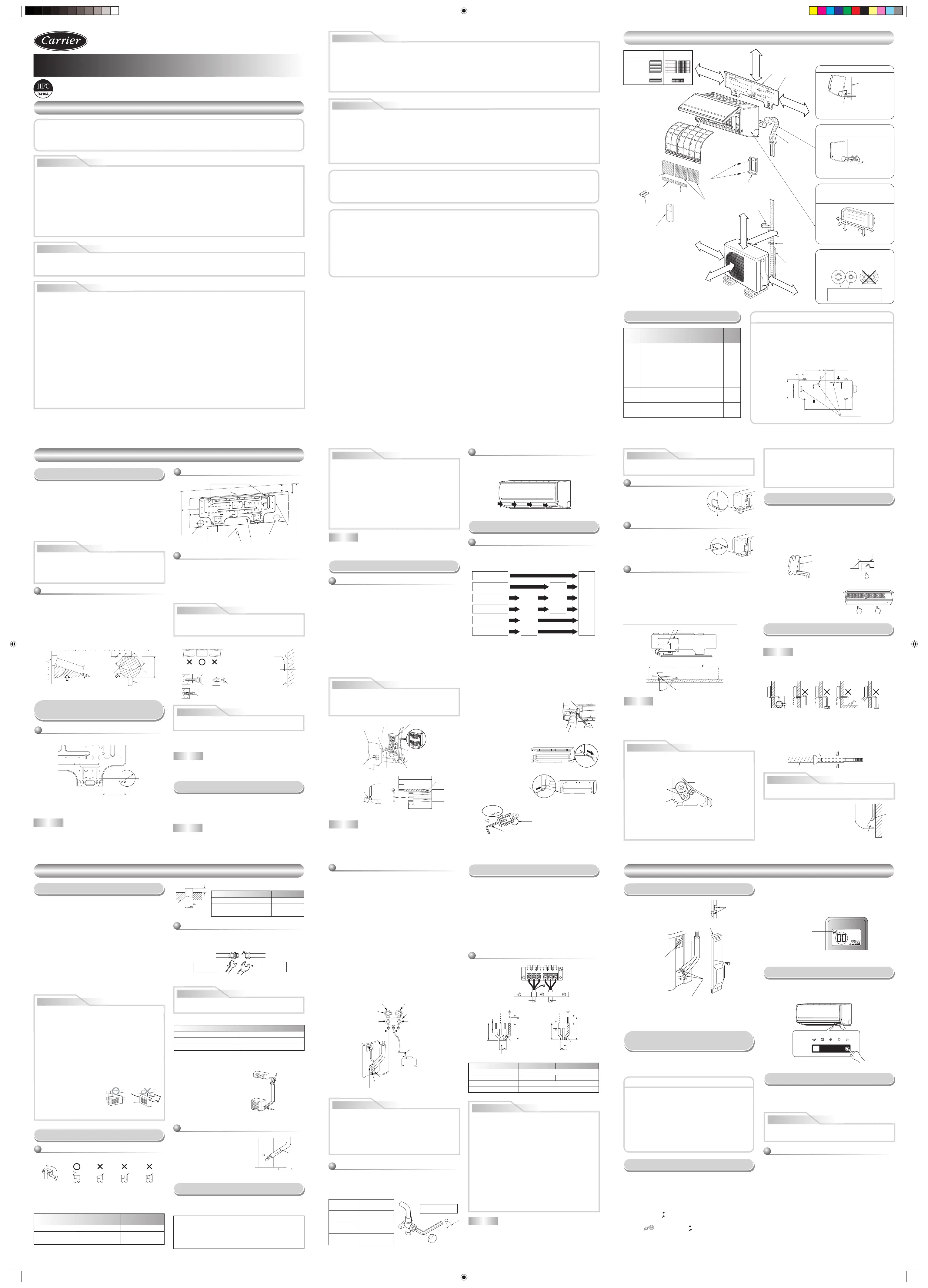
New refrigerant air conditioner installation
INSTALLATION DIAGRAM OF INDOOR AND OUTDOOR UNITSINSTALLATION DIAGRAM OF INDOOR AND OUTDOOR UNITS
Part
code
Parts name Q’ty
A
Refrigerant piping
Liquid side : Ø6.35 mm
Gas side : Ø9.52 mm
(42NQV025,
42NQV035)
: Ø12.70 mm
(42NQV045)
One
each
B
Pipe insulating material
(polyethylene foam, 6 mm thick)
1
C
Putty, PVC tapes
One
each
Optional Installation Parts
• Secure the outdoor unit with fi xing bolts and nuts if the unit is
likely to be exposed to a strong wind.
• Use Ø8 mm or Ø10 mm anchor bolts and nuts.
• If it is necessary to drain the defrost water, attach drain nipple
9 and cap water proof ! to the bottom plate of the outdoor
unit before installing it.
Fixing bolt arrangement of outdoor unit
INDOOR UNITINDOOR UNIT
Installation Place
• A place which provides the spaces around the indoor unit as
shown in the diagram
• A place where there are no obstacles near the air inlet and
outlet
• A place which allows easy installation of the piping to the
outdoor unit
• A place which allows the front panel to be opened
• The indoor unit shall be installed as top of the indoor unit
comes to at least 2 m height. Also, it must be avoided to put
anything on the top of the indoor unit.
• Direct sunlight to the indoor unit’s wireless receiver
should be avoided.
•
The microprocessor in the indoor unit should not be too
close to RF noise sources.
(For details, see the owner’s manual.)
Remote control
• A place where there are no obstacles such as a curtain that
may block the signal from the indoor unit
• Do not install the remote control in a place exposed to di-
rect sunlight or close to a heating source such as a stove.
• Keep the remote control at least 1 m apart from the nearest
TV set or stereo equipment. (This is necessary to prevent
image disturbances or noise interference.)
• The location of the remote control should be determined as
shown below.
m
5
m
5
54 °
4
5°
5
7 °
* 7 m
7m
(Top view)
* : Axial distance
Reception
range
Remote
control
Remote
control
(Side view)
Indoor unit
Indoor unit
Recep
tion range
The center of the pipe hole
is above the arrow.
65 mm
100 mm
Pipe hole
80 100 180
Cutting a Hole and Mounting
Installation Plate
NOTE
• When drilling a wall that contains a metal lath, wire lath or
metal plate, be sure to use a pipe hole brim ring sold sepa-
rately.
Cutting a hole
When installing the refrigerant pipes from the rear
Mounting the installation plate
How to install the air inlet grille on the
indoor unit
• When attaching the air inlet grille, the contrary of the
removed operation is performed.
Rear right
Rear left
g
nittuc-eiD
tils l
e
na
p
t
n
o
rf
g
n
i
gn
a
hC
e
s
oh niard
noitaraperp g
ni
p
i
P
Bottom left
Left
Bottom right
Right
Piping and Drain Hose Installation
* Since dewing results in a machine trouble, make sure to
insulate both connecting pipes. (Use polyethylene foam as
insulating material.)
Piping and drain hose forming
1. Die-cutting front panel slit
Cut out the slit on the leftward or right side of the front panel
for the left or right connection and the slit on the bottom left
or right side of the front panel for the bottom left or right con-
nection with a pair of nippers.
2. Changing drain hose
For leftward connection, bottom-leftward connection and
rearleftward connection’s piping, it is necessary to change
the drain hose and drain cap.
How to remove the drain cap
Clip the drain cap by
needle-nose pliers and
pull out.
Heat insulator
Drain hose
How to fi x the drain cap
1) Insert hexagon
wrench (4 mm)
in a center head.
4 mm
2) Firmly insert the drain cap.
Do not apply lubricating oil
(refrigerant machine oil) when
inserting the drain cap. Application
causes deterioration and drain
leakage of the plug.
Insert a hexagon
wrench (4 mm).
No gap
Firmly insert the drain hose and drain cap; otherwise, water
may leak.
In case of right or left piping
• After scribing slits of the front
panel with a knife or a making-off
pin, cut them with a pair of
nippers or an equivalent tool.
In case of bottom right or bottom left
piping
• After scribing slits of the front
panel with a knife or a
making-off pin, cut them with
a pair of nippers or an equivalent tool.
Pipe hole
62
85
82.5
170
Indoor unit
Thread
Hook
Weight
Pipe hole
Mounting screw
Hook
Hook
Installation
plate
Anchor bolt holes
2 m or more from floor
7
1
Slit
Slit
Left-hand connection with piping
• Bend the connecting pipe so that it is laid within 43 mm above
the wall surface. If the connecting pipe is laid exceeding 43
mm above the wall surface, the indoor unit may unstably be
set on the wall.
When bending the connecting pipe, make sure to use a
spring bender so as not to crush the pipe.
Bend the connecting pipe within a radius of 30 mm.
To connect the pipe after installation of the unit (fi gure)
80
270 mm
170 mm
m
m 3
4
(To the forefront of flare)
Liquid side
Outward form of indoor unit
R 30 mm (Use polisin (polyethylene)
core or the like for bending pipe.)
Use the handle of screwdriver, etc.
Gas side
NOTE
If the pipe is bent incorrectly, the indoor unit may unstably be
set on the wall.
After passing the connecting pipe through the pipe hole, con-
nect the connecting pipes to the auxiliary pipes and wrap the
facing tape around them.
• Bind the auxiliary pipes (two) and connecting cable with
facing tape tightly. In case of leftward piping and rear-
leftward piping, bind the auxiliary pipes (two) only with
facing tape.
Auxiliary pipes
Indoor unit
Connecting cable
Installation plate
• Carefully arrange pipes so that any pipe does not stick
out of the rear plate of the indoor unit.
• Carefully connect the auxiliary pipes and connecting
pipes to one another and cut off the insulating tape
wound on the connecting pipe to avoid double-taping
Indoor Unit Fixing
1. Pass the pipe through the hole in the wall and hook the
indoor unit on the installation plate at the upper hook.
2. Swing the indoor unit to right and left to confi rm that it is
fi rmly hooked up on the installation plate.
3. While pressing the indoor unit onto the wall, hook it at the
lower part on the installation plate. Pull the indoor unit to-
ward you to confi rm that it is fi rmly hooked up on the instal-
lation plate.
• For detaching the indoor unit
from the installation plate, pull
the indoor unit toward you while
pushing its bottom up at the
specifi ed parts.
PushPush
Drainage
1. Run the drain hose sloped downwards.
2. Put water in the drain pan and make sure that the water is
drained out of doors.
3.
When connecting extension drain hose, insulate the con-
necting part of extension drain hose with shield pipe.
NOTE
• The hole should be made at a slight downward slant on the
outdoor side.
50 mm
or more
Do not put the
drain hose end
into water.
Do not put the
drain hose end
in the drainage ditch.
Do not form the
drain hose into
a wavy shape.
Do not rise the
drain hose.
Extension drain hose
Inside the room
Drain hose
Shield pipe
Arrange the drain pipe for proper drainage from the unit.
Improper drainage can result in dew-dropping.
Wall
Drain
guide
Space for pipes
This air conditioner has the structure
designed to drain water collected
from dew, which forms on the back
of the indoor unit, to the drain pan.
Therefore, do not store the power cord
and other parts at a height above the
drain guide.
REQUIREMENT OF REPORT TO THE LOCAL POWER SUPPLIER
Please make absolutely sure that the installation of this appliance is reported to the local power supplier before installation.
If you experience any problems or if the installation is not accepted by the supplier, the service agency will take adequate
countermeasures.
When the installation plate is directly
mounted on the wall
1. Securely fi t the installation plate onto the wall by screwing it
in the upper and lower parts to hook up the indoor unit.
2. To mount the installation plate on a concrete wall with anchor
bolts, use the anchor bolt holes as illustrated in the below
fi gure.
3. Install the installation plate horizontally in the wall.
When installing the installation plate with a mounting screw,
do not use the anchor bolt holes. Otherwise, the unit may fall
down and result in personal injury and property damage.
Failure to fi rmly install the unit may result in personal injury
and property damage if the unit falls.
• In case of block, brick, concrete or similar type walls, make 5
mm dia. holes in the wall.
• Insert clip anchors for appropriate mounting screws
7.
NOTE
• Secure four corners and lower parts of the installation plate
with 4 to 6 mounting screws to install it.
Electrical Work
1. The supply voltage must be the same as the rated voltage
of the air conditioner.
2. Prepare the power source for exclusive use with the air
conditioner.
• This appliance can be connected to the mains in either of
the following two ways.
(1) Connection to fi p1-xed wiring:
A switch or circuit breaker which disconnects all
poles and has a contact separation of at least 3 mm
must be incorporated in the fi xed wiring. An approved
circuit breaker or switches must be used.
(2) Connection with power supply plug:
Attach power supply plug with power cord and plug it
into wall outlet. An approved power supply cord and
plug must be used.
NOTE
• Perform wiring works so as to allow a general wiring
capacity.
Wiring Connection
Wiring of the connecting cable can be carried out without
removing the front panel.
1. Remove the air inlet grille.
Open the air inlet grille upward and pull it toward you.
2. Remove the terminal cover and cord clamp.
3. Insert the connecting cable (according to the local cords)
into the pipe hole on the wall.
4. Take out the connecting cable through the cable slot on the
rear panel so that it protrudes about 15 cm from the front.
5. Insert the connecting cable fully into the terminal block and
secure it tightly with screws.
6. Tightening torque : 1.2 N·m (0.12 kgf·m)
7. Secure the connecting cable with the cord clamp.
8. Fix the terminal cover, rear plate bushing and air inlet grille
on the indoor unit.
How to connect the connecting cable
• Be sure to refer to the wiring system diagram labeled
inside the front panel.
• Check local electrical cords and also any specifi c wiring
instructions or limitations.
Installation plate
(Keep horizontal direction.)
Projection
15 mm or less
Anchor bolt
Clip anchor
(local parts)
5 mm dia. hole
Mounting screw
Ø4 x 25 R
7
OUTDOOR UNITOUTDOOR UNIT
Installation Place
1. Install the outdoor unit without anything blocking the air
discharging.
2. When the outdoor unit is installed in a place always
exposed to strong wind like a coast or on a high storey
of a building, secure the normal fan operation using a
duct or a windshield.
3. In particularly windy areas, install the unit such as to
avoid admission of wind.
4. Installation in the following places may result in
trouble.
Do not install the unit in such places.
• A place full of machine oil
• A saline-place such as the coast
• A place full of sulfi de gas
• A place where high-
frequency waves are
likely to be generated
as from audio equipment,
welders, and medical equipment
Strong
wind
Refrigerant Piping Connection
1. Cut the pipe with a pipe cutter.
2. Insert a fl are nut into the pipe and fl are the pipe.
• Projection margin in fl aring : A (Unit : mm)
Rigid (clutch type)
Obliquity Roughness Warp
90
Imperial (wing nut type)
Outer dia. of copper pipe R410A
Ø6.35 1.5 to 2.0
Ø9.52 1.5 to 2.0
Ø12.70 2.0 to 2.5
Die
Pipe
A
Align the centers of the connecting pipes and tighten the fl are
nut as far as possible with your fi ngers. Then tighten the nut
with a spanner and torque wrench as shown in the fi gure.
Tightening connection
Do not apply excess torque. Otherwise, the nut may crack
depending on the conditions.
(Unit : N·m)
Outer dia. of copper pipe Tightening torque
Ø6.35 mm 16 to 18 (1.6 to 1.8 kgf·m)
Ø9.52 mm 30 to 42 (3.0 to 4.2 kgf·m)
Ø12.70 mm 50 to 62 (5.0 to 6.2 kgf·m)
Evacuating
After the piping has been connected to the indoor unit, you
can perform the air purge together at once.
AIR PURGE
Evacuate the air in the connecting pipes and in the indoor
unit using a vacuum pump. Do not use the refrigerant in
the outdoor unit. For details, see the manual of the vacuum
pump.
Be sure to use a vacuum pump with counter-fl ow prevention
function so that inside oil of the pump does not fl ow backward
into pipes of the air conditioner when the pump stops.
(If oil inside of the vacuum pump enters the air conditioner,
which use R410A, refrigeration cycle trouble may result.)
1. Connect the charge hose from the manifold valve to the
service port of the packed valve at gas side.
2. Connect the charge hose to the port of the vacuum pump.
3. Open fully the low pressure side handle of the gauge
manifold valve.
4. Operate the vacuum pump to start evacuating. Perform
evacuating for about 15 minutes if the piping length is
20 meters.
(15 minutes for 20 meters) (assuming a pump
capacity of 27 liters per minute) Then confi rm that the
compound pressure gauge reading is –101 kPa (–76 cmHg).
5. Close the low pressure side valve handle of the gauge
manifold valve.
6. Open fully the valve stem of the packed valves (both gas
and liquid sides).
7. Remove the charging hose from the service port.
8. Securely tighten the caps on the packed valves.
Using a vacuum pump
• Open the valve stem all the way out, but do not try to open it
beyond the stopper.
• Securely tighten the valve stem cap with torque in the
following table:
Packed valve handling precautions
m
m 4
The hexagon wrench
is required.
Gas side
(Ø12.70 mm)
50 to 62 N·m
(5.0 to 6.2 kgf·m)
Gas side
(Ø9.52 mm)
30 to 42 N·m
(3.0 to 4.2 kgf·m)
Liquid side
(Ø6.35 mm)
16 to 18 N·m
(1.6 to 1.8 kgf·m)
Service port
9 to 10 N·m
(0.9 to 1.0 kgf·m)
Wiring Connection
1. Remove the valve cover from the outdoor unit.
2. Connect the connecting cable to the terminals as identifi ed
with their respective matched numbers on the terminal block
of indoor and outdoor unit.
3. When connecting the connecting cable to the outdoor unit
terminals, make a loop as shown in the installation diagram
of indoor and outdoor unit to prevent water coming in the
outdoor unit.
4. Insulate the unused cords (conductors) from any water
coming in the outdoor unit. Proceed them so that they do not
touch any electrical or metal parts.
Stripping length of the connecting cable
OTHERSOTHERS
Gas Leak Test
Setting of Remote Control
Selector Switch
Remote control selector switch
• A place which provides the spaces around the outdoor unit
as shown in the diagram
• A place which can bear the weight of the outdoor unit and
does not allow an increase in noise level and vibration
• A place where the operation noise and discharged air do not
disturb your neighbors
• A place which is not exposed to a strong wind
• A place free of a leakage of combustible gases
• A place which does not block a passage
• When the outdoor unit is to be installed in an elevated posi-
tion, be sure to secure its feet.
• An allowable length of the connecting pipe is up to 10 m for
38NYV025 and 15 m for 38NYV035, 38NYV045.
• An allowable height level is up to 8 m for 38NYV025 and
10 m for 38NYV035, 38NYV045.
• A place where the drain water does not raise any problems
Test Operation
To switch the TEST RUN (COOL) mode, press RESET button
for 10 seconds. (The beeper will make a short beep.)
Auto Restart Setting
The product was shipped with Auto Restart function in the
off position. Turn it on as required.
How to set the Auto Restart
This appliance must be connected to the main power supply by means of a circuit breaker or a switch with a contact
separation of at least 3 mm in all poles.
The installation fuse (25A) must be used for the power supply line of this
air conditioner.
CAUTION
To disconnect the appliance from the main power supply
• Exposure of unit to water or other moisture before installation could result in electric shock.
Do not store it in a wet basement or expose to rain or water.
• After unpacking the unit, examine it carefully for possible damage.
• Do not install in a place that can increase the vibration of the unit. Do not install in a place that can amplify the noise level
of the unit or where noise and discharged air might disturb neighbors.
• To avoid personal injury, be careful when handling parts with sharp edges.
• Please read this installation manual carefully before installing the unit. It contains further important instructions for proper
installation.
Remark per EMC Directive 89/336/EEC
To prevent fl icker impressions during the start of the compressor (technical process), following installation conditions does
apply.
1. The power connection for the air conditioner has to be done at the main power distribution. This distribution has to be of
an impedance.
Normally, the required impedance is reached at a 32A fusing point. Air conditioner fuse has to be 16A max.!
2. No other equipment should be connected to this power line.
3. For detailed installation acceptance, please contact your power supplier whether its restriction does apply for products
like washing machines, air conditioners or electric ovens.
4. For power details of the air conditioner, refer to the rating plate of the product.
600 mm
90 mm
125 mm
108 mm
32.5 mm
86 mm
102 mm
320 mm
7 mm
30
Air outlet
Air inlet
Drain outlet
Insert the cushion between the indoor
unit and wall, and tilt the indoor unit
for better operation.
For the rear left and left piping
Wall
Insulate the refrigerant pipes
separately with insulation, not
together.
2
3
8
6
4
Make sure to run the drain hose
sloped downward.
Do not allow the drain hose to get
slack.
Cut the piping
hole sloped
slightly.
The auxiliary piping can be connected
to the left, rear left, rear right, right,
bottom right or bottom left.
Right
Rear
right
Bottom
right
Rear
left
Bottom left
Left
6 mm thick heat resisting
polyethylene foam
1
Batteries
Pan head
wood screw
Remote control
holder
Vinyl tape
Apply after carrying
out a drainage test.
Wireless remote control
Saddle
Extension
drain hose
(Not available,
provided by installer)
Shield pipe
Filter
(Attach to the front panel.)
Air fi lter
Hook
Installation
plate
Hook
65 mm or more
170 mm or more
170 mm
or more
600 mm
or more
100 mm or
more
100 mm or more
600 mm or mor
e
600 mm or
more
Remark :
• Detail of accessory and installation parts can
see in the accessory sheet.
NOTE
• Wire type : More than H07RN-F or 245 IEC66
NOTE
• Use stranded wire only.
• Wire type : H07RN-F or more
Outer dia.
of copper pipe
R410A tool used
Conventional tool
used
Ø6.35 0 to 0.5 1.0 to 1.5
Ø9.52 0 to 0.5 1.0 to 1.5
Ø12.70 0 to 0.5 1.0 to 1.5
Use a wrench to secure. Use a torque wrench to tighten.
Flare nut
Half union
Internally
threaded side
Externally
threaded side
• Tightening torque of fl are pipe connections
The operating pressure of R410A is higher than that of R22
Flare at
indoor unit side
Flare at
outdoor unit side
(approx. 1.6 times). It is therefore
necessary to fi rmly tighten the
fl are pipe connecting sections
(which connect the indoor and
outdoor units) up to the specifi ed
tightening torque. Incorrect
connections may cause not only
a gas leakage, but also damage
to the refrigeration cycle.
1. How to shape the pipes
Shape the pipes along the incused
line on the outdoor unit.
2. How to fi t position of the pipes
Put the edges of the pipes to the
place with a distance of 85 mm
from the incused line.
Shaping pipes
Incused line
RESET
RESET button
1. After determining the pipe hole position on the mounting
plate (¨), drill the pipe hole (Ø65 mm) at a slight downward
slant to the outdoor side.
Earth line
Connecting cable
about 15 cm
Stripping length of the connecting cable
Connecting cable
Screw
Screw
Earth line
Terminal block
Screw
Cord clamp
Terminal cover
1
2
3
1
3
2
10 mm
10 mm
50 mm
110 mm
Remote Control A-B Selection
Note : 1. Repeat above step to reset Remote Control to be
A.
2. Remote Control A has not “A” display.
3. Default setting of Remote Control from factory is
A.
“B” Display
“00” Display
Press
(unhook)
Hook
Hook here.
1
2
Installation plate
1
Flaring
Connecting cable
Power cord
Terminal block
Earth line Earth line
Connecting cable Power cord
01
01
0
1
01
30 30
40 40
L
N
1
2
3
Model 42NQV025 42NQV035, 42NQV045
Power source 50Hz, 220 – 240 V Single phase
Maximum running current 8A 11A
Plug socket & fuse rating 25A
Power cord H07RN-F or 245 IEC66 (1.5 mm
2
or more)
Check places for
the outdoor unit.
Electric parts cover
Valve cover
Check places for
the indoor unit.
at the joint; moreover, seal the joint with the vinyl tape,
etc.
• Since dewing results in a machine trouble, make sure to
insulate both connecting pipes. (Use polyethylene foam
as insulating material.)
•
When bending a pipe, carefully do it, not to crush it.
FILTER
56
025H, 035H,
045H
035M, 045M
6
5
1110251111 (ENGLISH)
How to remove the drain hose
• The drain hose can be removed by
take off screw, after that twisting and
pulling.
• When removing the drain hose, be
careful of any sharp edges of steel
plate. The edges can cause injuries.
DANGER
CAUTION
CAUTION
WARNING
CAUTION
CAUTION
CAUTION
CAUTION
CAUTION
CAUTION
CAUTION
CAUTION
CAUTION
CAUTION
CAUTION
CAUTION
NOTE
: Connecting cable
• Wire type : More than H07RN-F or 245 IEC66
• Wrong wiring connection may cause some electrical
parts burn out.
• Be sure to comply with local cords on running the wire
from indoor unit to outdoor unit (size of wire and wiring
method, etc.).
• Every wire must be connected fi rmly.
• This installation fuse (25A) must be used for the power
supply line of this air conditioner.
• If incorrect or incomplete wiring is carried out, it will
cause an ignition or smoke.
• Prepare the power supply for exclusive use with the air
conditioner.
• This product can be connected to the mains.
Connection to fi xed wiring: A switch which disconnects
all poles and has a contact separation of at least 3 mm
must be incorporated in the fi p1-xed wiring.
• KEEP IMPORTANT 4 POINTS FOR PIPING WORK.
(1) Take away dust and moisture (inside of the connecting
pipes).
(2) Tighten the connections (between pipes and unit).
(3) Evacuate the air in the connecting pipes using a
VACUUM PUMP.
(4) Check gas leak (connected points).
To separate using of remote control for each indoor unit in
case of 2 air conditioners are installed nearly.
Remote Control B Setup.
1. Press RESET button on the indoor unit to turn the air
conditioner ON.
2. Point the remote control at the indoor unit.
3. Push and hold button on the Remote Control by the tip of
the pencil. “00” will be shown on the display.
4. Press
during pushing . “B” will show on the display
and “00” will disappear and the air conditioner will turn
OFF. The Remote Control B is memorized.
• When two indoor units are installed in the same room or
adjacent two rooms, if operating a unit, two units may
receive the remote control signal simultaneously and
operate. In this case, the operation can be preserved
by setting either one indoor unit or remote control to B
setting. (Both are set to A setting in factory shipment.)
• The remote control signal is not received when the
settings of indoor unit and remote control are different.
• There is no relation between A setting/B setting and A
room/B room when connecting the piping and cables.
When two indoor units are installed in the separated
rooms, it is not necessary to change the selector
switches.
• Check the fl are nut connections for the gas leak with a gas
leak detector or soap water.
This product is designed so that, after a power failure, it can
restart automatically in the same operating mode as before the
power failure.
•
Press and hold the RESET button for about 3 seconds. After
3 seconds, the electronic beeper makes three short beeps to
tell you the Auto Restart has been selected.
•
To cancel the Auto Restart, follow the steps described in the
section Auto Restart Function of the owner’s manual.
Information
Packed valve at liquid side
Service port (Valve core (Setting pin))
Packed valve at gas side
Vacuum
pump
Vacuum pump adapter for
counter-fl ow prevention
(For R410A only)
Charge hose
(For R410A only)
Handle Hi
(Keep full closed)
Manifold valve
Pressure gauge
Compound pressure gauge
Handle Lo
Charge hose
(For R410A only)
Connecting pipe
–101 kPa
(–76 cmHg)
Filter
Filter
5
Filter
1110251111-EN.indd 11110251111-EN.indd 1 1/16/07 9:13:46 AM1/16/07 9:13:46 AM

50 mm
or more
Do not put the
drain hose end
into water.
Do not put the
drain hose end
in the drainage ditch.
Do not form the
drain hose into
a wavy shape.
Do not rise the
drain hose.
No levante la
manuguera de drenaje.
No doble la manguera de
drenaje en forma de ondas.
50 mm
o más
No ponga el extremo
de la manguera de
drenaje en el agua.
No ponga el extremo de
la manguera de drenaje
en la acequía de renaje.
Installation plate
(Keep horizontal direction.)
Projection
15 mm or less
Anchor bolt
Clip anchor
(local parts)
5 mm dia. hole
Mounting screw
Ø4 x 25 R
7
Placa de instalación
(Mantenga la posición horizontal.)
Orifi cio, 5 mm diá
Gancho de anclaje
(partes locales
Tornillo de montaje
Ø4 x 25R
Perno de anclaje
Proyección
15 mm o menos
• Nunca modifi que esta unidad quitando uno de las etiquetas de seguridad o puenteando uno de los interruptores de
interbloqueo de seguridad.
• No instale esta unidad en un lugar que no sea capaz de resistir el peso de la unidad.
Si la unidad se cayera podría causar daños personales o materiales.
• Antes de hacer un trabajo eléctrico, instale un enchufe aprobado al cable de suministro de alimentación. Y asegúrese
de que el equipo está conectado a tierra.
• El aparato deberá instalarse según las regulaciones de cableado nacional.
Si detectara algún daño, no instale la unidad. Póngase en contacto con su concesionario Carrier inmediatamente.
ACONDICIONADOR DE AIRE (TIPO SPLIT)
MANUAL DE INSTALACIÓNMANUAL DE INSTALACIÓN
PRECAUCIONES SOBRE SEGURIDADPRECAUCIONES SOBRE SEGURIDAD
Para el uso público general
El cable de alimentación de las piezas del sistema instaladas en el exterior debe ser al menos cable fl exible enfundado en
policloropreno (modelo H07RN-F) o del tipo 245 IEC66 (1,5 mm
2
o más). (Debe instalarse según las normas de instalación
eléctrica de cada país.)
• ESTE SISTEMA AIRE ACONDICIONADO UTILIZA EL NUEVO REFRIGERANTE HFC (R410A) QUE NO DAÑA
LA CAPA DE OZONO.
El refrigerante R410A puede contaminarse de impurezas, como agua, membrana oxidante y aceites, p2-ya que su presión es
aproximadamente 1,6 veces superior a la del refrigerante R22. Gracias al uso del nuevo refrigerante, también se emplea
un aceite distinto para el aparato de refrigeración. Por lo tanto, durante las tareas de instalación, asegúrese de que no
se introduzca agua, polvo, otro tipo de refrigerante ni aceite del aparato de refrigeración en el ciclo de refrigeración del
sistema de aire acondicionado que emplea el nuevo refrigerante.
Para impedir que el refrigerante se mezcle con el aceite del aparato de refrigeración, los tamaños de las secciones
de conexión de los orifi cios de carga de la unidad principal o de las herramientas de instalación son diferentes de las
correspondientes al refrigerante convencional. Para la conexión de tuberías, utilice materiales nuevos, limpios, estancos
a alta presión y fabricados exclusivamente para R410A, a fi n de que no se introduzca agua ni polvo. Asimismo, no utilice
la tubería existente, p2-ya que presenta problemas de pérdidas y admisión de impurezas.
• SOLAMENTE PARA EL USO DE PERSONAS CUALIFICADAS.
• DESACTIVE LA FUENTE DE ALIMENTACIÓN PROVISTA Y EL CORTACIRCUITOS ANTES DE INTENTAR REALIZAR
CUALQUIER TRABAJO ELÉCTRICO. ASEGURESE DE QUE TODOS LOS INTERRUPTORES DE ALIMENTACIÓN Y
CORTACIRCUITOS ESTÉN DESACTIVADOS, SI NO LO HACE PODRÍA CAUSAR DESCARGAS ELÉCTRICAS.
• CONECTE EL CABLE DE CONEXIÓN CORRECTAMENTE. SI ESTE CABLE FUESE CONECTADO ERRONEAMENTE,
SE PODRÍAN DAÑAR LAS PARTES ELÉCTRICAS.
• REVISE EL CABLE A TIERRA QUE NO ESTE ROTO NI DESCONECTADO ANTES DE LA INSTALACIÓN.
• NO INSTALE CERCA DE CONCENTRACIONES DE COMBUSTIBLE DE GAS O VAPORES DE GAS. SI FALLA EN
CUMPLIR CON ESTA INSTRUCCION PODRIA RESULTAR EN UN INCENDIO O UNA EXPLOSIÓN.
• PARA EVITAR EL RECALENTAMIENTO DE LA UNIDAD INTERIOR Y LA CAUSA DE POSIBLES INCENCIOS, COLOQUE
LA UNIDAD BIEN LEJOS (A MÁS DE 2 METROS) DE FUENTES DE CALEFACCIÓN TALES COMO RADIADORES,
CALEFACTORES, ESTUFAS, HORNOS, ETC.
• CUANDO MUEVA EL ACONDICIONADOR DE AIRE PARA INSTALARLO EN OTRO LUGAR, TENGA CUIDADO DE NO
OBTENER EL REFRIGERANTE ESPECIFICADO (R410A) CON ALGUN OTRO CUERPO GASEOSO EN EL CICLO DE
REFRIGERACIÓN. SI EL AIRE O ALGUN OTRO GAS SE MEZCLARA CON EL REFRIGERANTE, LA PRESIÓN DEL GAS
EN EL CICLO DE REFRIGERACIÓN SE VUELVE ANORMALMENTE ALTA Y ESTO RESULTANDO EN CAUSAR UN
ESTALLIDO DE LA TUBERÍA Y DAÑOS EN LAS PERSÓNAS.
• EN EL CASO DE QUE EL GAS REFRIGERANTE ESCAPARA DE LA TUBERÍA DURANTE EL TRABAJO DE INTALACIÓN,
INMEDIATAMENTE DEJE QUE PASE AIRE FRESCO EN LA HABITACIÓN. SI ESTE GAS REFRIGERANTE ES
CALENTADO POR EL FUEGO O ALGO SIMILAR, CAUSARA LA GENERACIÓN DE UN GAS VENENOSO.
Instalación de sistema de aire acondicionado con un nuevo refrigerante
DIAGRAMA DE INSTALACIÓN DE LA UNIDAD INTERIOR Y EXTERIORDIAGRAMA DE INSTALACIÓN DE LA UNIDAD INTERIOR Y EXTERIOR
Código
de pieza
Nombre de partes Ctdad.
A
Tubería de refrigerante
Lado líquido : Ø6,35 mm
Lado de gas : Ø9,52 mm
(42NQV025,
42NQV035)
: Ø12,70 mm
(42NQV045)
Cada
uno
B
Material aislante de tuberías
(espuma de polietileno de 6 mm
de grosor)
1
C
Masilla, cintas de PVC
Cada
uno
Piezas de Instalación Opcional
• Proteja la unidad exterior con los tornillos y tuercas de
fi jación si va a permanecer expuesta a la acción de
vientos fuertes.
• Utilice tornillos y tuercas de anclaje de Ø8 mm o Ø10
mm.
• Si fuera necesario vaciar el agua descongelada, conecte
el codo de drenaje 9 y la tapa impermeable ! en la
placa inferior de la
unidad exterior
antes de instalarla.
Fijación de tornillos de la unidad exterior
UNIDAD INTERIORUNIDAD INTERIOR
Lugar de Instalación
• Un lugar que brinde espacio alrededor de la unidad interior
tal como se muestra en el diagrama
• Un lugar en el que no haya obstáculos cerca de la entrada
y salida de aire
• Un lugar que permita una instalación fácil de la tubería para
la unidad exterior
• Un lugar que permita que el panel delantero se abra
• La unidad interior debe instalarse cuando su parte superior
alcance al menos los 2 m de altura. También debe evitarse
colocar objetos sobre la unidad interior.
• Se deberá evitar la luz directa del sol sobre el receptor de
control a distancia de la unidad interior.
• El microprocesador de la unidad interior no deberá estar
tan cerca de las fuentes de ruido RF.
(Para los detalles, vea el manual del usuario.)
Control remoto
• Un lugar en el que no haya obstáculos tal como una cor-
tina que pudiese bloquear las señales del unidad interior
• No instale el control remoto en un lugar expuesto a la luz
directa del sol o ceraca de una fuente de calor, por ejemplo
una estufa.
• Mantenga el control remoto por lo menos a 1 m de distan-
cia de su equipo de TV o estéreo. (Esto es necesario para
evitar interrupciones o ruidos de interferencia.)
• La ubicación del control remoto deberá determinarse tal
como se ilustra abajo.
Corte de un Orifi cio y Montaje
de la Placa de Instalación
NOTA
• Cuando la perforación de una pared que contenga listones,
listones de alambre o placas de metal, asegúrese de utilizar
un anillo de borde como molde del orifi cio de la tubería
vendido por separado.
Corte de un orifi cio
Cuando instale las tuberías refrigerantes desde la parte pos-
terior
Montaje de la placa de instalación
Procedimiento para instalar la rejilla de
entrada de aire en la unidad interior
• Para instalar la rejilla de entrada de aire p2-ha de realizarse el
procedimiento inverso a su extracción.
Instalación la Tubería y el
Tubo de Desagüe
* Como la condensación produce problemas en el equipo,
asegúrese de aislar las dos tubarías de conexión. (Utilice
espuma de polietileno como material aislante.)
Formación la tubería y el tubo de desagüe
1. Tapa precortada
Corte con unos alicates la pestaña en el lado izquierdo o de-
recho del panel frontal para la conexión izquierda o derecha
y la pestaña en el lado inferior izquierdo o derecho del panel
frontal para la conexión inferior izquierda o derecha.
2. Cambio del tubo del desagüe
Para los desagües de las conexiones izquierda, inferior iz-
quierda y posterior izquierda, es necesario cambiar el tubo y
la tapa del desagüe.
Cómo quitar la tapa de drenaje
Sujete la tapa de drenaje
utilizando alicantes pun-
tiagudos y sáquela.
Forma de fi jar el tapón de desagüe
1) Inserte una llave
hexagonal (4 mm)
en el centro.
4 mm
2) Inserte fi rmemente el tapón de desagüe.
Para evitar pérdidas de agua, inserte con fi rmeza el tubo y
la tapa del desagüe.
Para las tuberías derecho o izquierdo
• Después de trazar un surco con un
cuchillo o un punzón alrededor de
la pestaña del panel frontal, córtela
con unas tijeras o una herramienta
similar.
Para las tuberías inferior derecho o
inferior izquierdo
• Después de trazar un surco con
un cuchillo o un punzón
alrededor de la pestaña del
panel frontal, córtela con unas
tijeras o una herramienta similar.
Conexión del lado izquierdo de la tubería
• Doble la tubería de conexión de tal manera que quede
tendida entre 43 mm sobre la superfi cie de la pared. Si la
tubería de conexión fuese tendida más allá de los 43 mm
sobre la superfi cie de la pared, la unidad interior podría ser
inestable en la pared. Cuando doble la tubería de conexión,
asegúrese de utilizar un torcedor de resortes para no estrujar
la tubería.
Doble la tubería de conexión dentro de un radio de 30 mm.
Conexión de la tubería después de la instalación de la unidad
(fi gura)
NOTA
Si la tubería fuese incorrectamente doblada, la unidad interior
podría instalarse de forma inestable sobre la pared.
Después de pasar la tubería de conexión a través del orifi cio de
la tubería, conecte la tubería de conexión a las tuberías auxilia-
res y envuelva con cinta para cubrir alrededor de las mismas.
•
Encinte las tuberías auxiliares (dos) y el cable de conexión
fuertemente. En caso de tubería por el lado izquierdo y por
el lado posterior izquierdo, encinte solamente las tuberías
auxiliares (dos).
Auxiliary pipes
Indoor unit
Connecting cable
Installation plate
• Cuidadosamente arregle las tuberías de tal manera que
ninguna de ellas sobresalga de la placa posterior de la
unidad interior.
• Conecte cuidadosamente las tuberías auxiliares y las
tuberías de conexión a cada una y corte la cinta aisladora
en la tubería de conexión para evitar la doble cinta en la
Instalación de la Unidad Interior
1. Pase la tubería a través del orifi cio de la pared, y enganche
la unidad interior sobre la placa de instalación en los
ganchos superiores.
2. Mueva la unidad interior hacia la derecha e izquierda para
confi rmar que esté fi rmemente enganchado en la placa de
instalación.
3. Mientras presiona la unidad interior sobre la pared por
la parte inferior, engánchelo hacia arriba en la placa de
instalación por la parte inferior. Tire la unidad interior dirigida
hacia Ud por la parte inferior para confi rmar que esté
fi rmemente enganchado sobre la placa de instalación.
• Para desmontar la unidad interior
de la placa de instalación, tire de
la unidad interior dirigida hacia Ud
mientras presiona la parte inferior
por las partes especifi cadas.
Drenaje
1. Coloque la manguera de drenaje inclinada hacia abajo.
2. Ponga agua en el depósito de drenaje y asegúrese que el
agua se drene hacia afuera.
3. Cuando conecte la manguera de drenaje de extensión,
aisle la parte de la conexión de la manguera de drenaje de
extensión con la protección de la tubería.
NOTA
• El orifi cio deberá hacerse inclinado levemente hacia abajo
al lado exterior.
Arregle la tubería de drenaje para el drenaje apropiado de
la unidad.
El drenaje incorrecto podría causar desperfectos.
Este acondicionador de aire tiene la
estructura designada para drenar el
agua colectada de la condensación,
que se forma en la parte posterior de
la unidad, para la bandeja de drenaje.
Por lo tanto, no almacene el cable de
alimentación y otras partes en una
altura sobre la guía de drenaje.
Cuando la placa de instalación es
directamente montada sobre la pared
1. Fije fi rmemente la placa de instalación sobre la pared
atornillando las partes superior e inferior para enganchar la
unidad interior.
2. Para montar la placa de instalación sobre una pared de
hormigón con tacos, utilice los orifi cios para tacos tal como
se muestra en la fi gura de abajo.
3. Instale la placa de instalación horizontalmente en la pared.
Cuando instale la placa de instalación con un tornillo de
montaje no utilice el orifi cio del cerrojo de áncora. Si no, la
unidad se podría caer y resultar en daños personales y en
daños de propiedad.
Si no instala fi rmemente la unidad podría causar daños
personales o materiales.
• En caso de paredes de bloques, ladrillos, hormigón o de tipo
similar, haga orifi cios un diámetro de 5 mm en la pared.
• Inserte tacos para tornillos de montaje
7 apropiados.
NOTA
• Fije las cuatro esquinas y partes inferiores de la placa de
instalación con 4 u 6 tornillos de montaje.
Trabajo Eléctrico
1. El suministro de voltaje deberá ser igual al del voltaje
nominal del acondicionador de aire.
2. Prepare la fuente de alimentación para el uso exclusivo
con el acondicionador de aire.
• Este sistema puede conectarse a la corriente de dos
formas distintas.
(1) Conexión a cable fi jo:
Es preciso incorporar al cable fi jo un interruptor
o disyuntor que desconecte todos los polos y
disponga de una separación de contacto de 3 mm
como mínimo. Es necesario utilizar un disyuntor o
interruptores homologados.
(2) Conexión mediante un enchufe:
Conecte un cable de alimentación con enchufe y
enchúfelo en una toma de corriente de pared. Deben
utilizarse un cable de alimentación y un enchufe
homologados.
NOTA
• Haga el trabajo de cableado de modo que deje una
capacidad generosa de cableado.
Conexión de Cables
El cableado del cable de conexión puede realizarse sin
quitar el panel frontal.
1. Extraiga la rejilla de entrada de aire.
Tire de la rejilla de entrada de aire hacia fuera para abrirla.
2. Quite la tapa de los terminales y el cable con abrazadera.
3. Inserte el cable de conexión (según los códigos locales) en
el orifi cio de la tubería de la pared.
4. Saque el cable de conexión a través de la ranura del cable
del panel posterior hasta que sobresalga aproximadamente
15 cm.
5. Inserte el cable de conexión completamente en el bloque
de terminales y asegúrelo fuertemente con un tornillo.
6. Tensamiento de torsión a par : 1,2 N·m (0,12 kgf·m)
7.
Asegure el cable de conexión con el cable con abrazadera.
8. Fije la cubierta del terminal, el cojinete de la placa trasera y
la rejilla de entrada de aire de la unidad interior.
Cómo conectar el cable de conexión
• Asegúrese de consultar con la etiqueta del diagrama
del sistema de cableado en el interior del panel frontal.
• Compruebe los códigos eléctricos locales, así como las
instruciones o limitaciones específi cas del cableado.
UNIDAD EXTERIORUNIDAD EXTERIOR
Lugar de Instalación
1. Instale la unidad exterior sin que nada bloquee la
descarga del aire.
2. Cuando la unidad exterior es instalada en un lugar
expuesto siempre al viento fuerte como una costa
o en la parte superior de un edifi cio, asegure el
funcionamiento normal del ventilador utilizando un
conducto o una protección para el viento.
3. Especialmente en una zona de mucho viento, instale la
unidad de forma que se evite la admisión del viento.
4. La instalación en los siguientes emplazamientos puede
resultar problemática.
No instale la unidad en los siguientes emplazamientos.
• Un lugar expuesto a aceite de máquinas
• Un lugar salino, como la costa
• Un emplazamiento expuesto a gas de sulfuro
• Un lugar donde se puedan generar con facilidad
ondas de alta frecuencia,
como por ejemplo, las
producidas por un equipo
de audio, soldadores y
equipos médicos
Conexión de la Tubería Refrigerante
1. Corte la tubería con un cortatubos para tubería.
2. Inserte una tuerca y abocine la tubería.
•
Margen de proyección de ensanchamiento : A
(Unidad : mm)
Rigida (tipo embrague)
Imperial (tuerca de tipo mariposa)
Diámetro externo de tubería
de cobre
R410A
Ø6,35 1,5 a 2,0
Ø9,52 1,5 a 2,0
Ø12,70 2,0 a 2,5
Alinee la tubería de conexión y apriete a fondo la tuerca con
sus dedos. Luego apriete la tuerca con una Ilave de tuercas y
una Ilave inglesa de torsión tal como se muestra en la fi gura.
Apriete de la tubería
No aplique demasiada torsión. De otra manera, la tuerca
podría quebrarse según las condiciones de instalación.
(Unidad : N•m)
Diámetro externo de tubería
de cobre
Tensamiento de torsión a par
Ø6,35 mm 16 a 18 (1,6 a 1,8 kgf·m)
Ø9,52 mm 30 a 42 (3,0 a 4,2 kgf·m)
Ø12,70 mm 50 a 62 (5,0 a 6,2 kgf·m)
• TENGA EN CUENTA LOS 4 PUNTOS ESENCIALES
DE LA INSTALACIÓN TUBERÍAS.
(1) Limpie el polvo y humedad (del interior de las tuberías
de conexión).
(2) Conexión tensa (entre las tuberías y la unidad).
(3) Evacue el aire de las tuberías de conexión utilizando
la BOMBA DE VACÍO.
(4) Revise si hay fugas de gas (puntos conectados).
Evacuación
Una vez que la tubería se p2-ha conectado a la unidad interior,
puede realizar una purga de aire.
PURGA DE AIRE
Evacue el aire de la tuberías de conexión y en la unidad
interior utilizando la bomba al vacío. No utilice el refrigerante
en la unidad exterior. Para los detalles, vea el manual de la
bomba al vacío.
Cerciórese de utilizar una bomba de vacío con función de
prevención de contracorriente para que el aceite interno de la
bomba no retroceda a las tuberías del sistema aire acondicio-
nado cuando la bomba se detenga.
(Si se introduce aceite interno de la bomba de vacío en el
sistema de aire acondicionado que utiliza R410A, puede pro-
ducirse una avería en el ciclo de refrigeración.)
1. Conecte el manguito de carga de la válvula distribuidora al
orifi cio de salida de la válvula de servicio del lado de gas.
2. Conecte el manguito de carga al orifi cio de la bomba al
vacío.
3. Abra completamente el mando lateral de baja presión de la
válvula distribuidora del manómetro.
4. Accione la bomba de vacío para iniciar la evacuación.
Realice la evacuación durante 15 minutos si la longitud de
la tubería es de 20 metros. (15 minutos para 20 metros)
(sobre la base de que la bomba tenga una capacidad de
27 litros por minuto) A continuación, confi rme que la lectura
compuesta del manómetro sea de –101 kPa (–76 cmHg).
5. Cierre el mando de la válvula lateral de baja presión del
distribución del manómetro.
6. Abra completamente el vástago de válvula de las válvulas
de servicio de gas y líquido.
7. Retire el manguito de carga del orifi cio de salida.
8. Cierre fi rmemente las tapas de las válvulas de servicio.
Uso de la bomba al vacío
• Abra el vástago de la válvula completamente hacia fuera,
pero sin avanzar más allá del retén.
• Apriete la tapa del vástago de la válvula con el par que se
indica en la tabla siguiente:
Precauciones de uso de las válvulas de
servicio
Lado de gas
(Ø12,70 mm)
50 a 62 N·m
(5,0 a 6,2 kgf·m)
Lado de gas
(Ø9,52 mm)
30 a 42 N·m
(3,0 a 4,2 kgf·m)
Lado líquido
(Ø6,35 mm)
16 a 18 N·m
(1,6 a 1,8 kgf·m)
Orifi cio de
salida
9 a 10 N·m
(0,9 a 1,0 kgf·m)
Conexión de Cables
1. Extraiga la cubierta de la válvula de la unidad exterior.
2. Conecte el cable de conexión a los terminales tal como se
identifi can con sus respectivos números correspondientes
en el bloque de terminales de la unidad interior y exterior.
3. Cuando conecte el cable de conexión al terminal de la
unidad exterior, haga un bucle como se muestra en la
ilustración del diagrama de instalación de la unidad interior
del agua interior que viene a la unidad exterior.
4. Aísle los cables no utilizados (conductores) del agua
proveniente de la unidad exterior. Evite que estén en
contacto con cualquier pieza eléctrica o de metal.
Pelado del cable de conexión
• Las conexiones del cableado incorrecto podrían causar
que se quemen algunas de las piezas eléctricas.
• Asegúrese de seguir los códigos locales al conectar la
unidad interior a la exterior (tamaño del cable, método
de cableado, etc.).
• Cada cable deberá conectarse fi rmemente.
• El fusible de instalación (25A) debe utilizarse como
conducto de suministro de energía de esta unidad de
aire acondicionado.
• Si se lleva a cabo un cableado incorrecto o incompleto,
puede calcinarse o humear.
• Disponga la toma de corriente exclusivamente para el
uso de la unidad de aire acondicionado.
•
Este producto puede conectarse a la corriente eléctrica.
Conexión al cable fi jo: Debe añadirse al cable fi jo un
interruptor que desconecte todos los polos y tenga una
separación del contacto de al menos 3 mm.
OTROSOTROS
Comprobación de Fugas
• Compruebe los escapes de gas con un detector de escapes
o agua enjabonada en las conexiones con tuercas.
NOTA : Cable de conexión
• Tipo de cable : Más de H07RN-F o 245 IEC66
Confi guración del interruptor de
selección del mando a distancia
Cuando se instalan dos unidades interiores en habitaciones
separadas, no es necesario cambiar los interruptores de
selección.
• Cuando se instalan dos unidades interiores en la
misma habitación o en dos habitaciones adyacentes,
al conectar una de ellas, puede que las dos unidades
reciban simultáneamente la señal del mando a distancia
y empiecen a funcionar. En este caso, se puede evitar
el funcionamiento de una de las dos, confi gurando una
de las unidades interiores y el mando a distancia en la
posición B (ambas vienen confi guradas de fábrica en la
posición A).
• La señal del mando a distancia no se recibe cuando
la confi guración de la unidad interior y la del mando a
distancia son diferentes.
• No existe relación alguna entre confi guración A/con-
fi guración B y habitación A/habitación B al conectar la
conducción y los cables.
Interruptor de selección del mando
a distancia
• Un lugar que tenga espacios alrededor de la unidad exterior
tal como se muestra en el diagrama
• Un lugar que pueda resistir el peso de la unidad exterior y
que no permita el aumento del nivel de ruido y vibración
• Un lugar en donde el ruido de funcionamiento y el aire des-
cargado no moleste a sus vecinos
• Un lugar que no sea expuesto al viento fuerte
• Un lugar libre de fi ltración de gases combustibles
• Un lugar que no bloquee un pasaje
• Cuando la unidad exterior tenga que instalarse en una
posición elevada, cerciórese de asegurar las patas.
• Una longitud tolerable de la tubería de conexión es de hasta
10 m para 38NYV025 y 15 m para 38NYV035, 38NYV045.
• El nivel máximo de cabeza permisible es de 8 m para
38NYV025 y 10 m para 38NYV035, 38NYV045.
• Un lugar en donde el agua drenada no de lugar a ningún
problemas
Prueba de Operación
Para conectar el modo de TEST RUN (COOL), presione y
mantenga presionado el botón RESET durante aproximada-
mente 10 segundos. (La máquina emitirá un bip corto.)
Ajuste de Reinicio Automático
Este producto está diseñado para que después de un fallo de
alimentación, se pueda reiniciar automáticamente al mismo
modo operación tal como estaba antes del fallo eléctrico.
El producto fue embarcado con la función de reinicio
automático en la posición de desactivado. Actívelo según
se requiera.
Como ajustar el reinicio automático
•
Presione y mantenga presionado el botón RESET durante
aproximadamente 3 segundos. Después de 3 segundos, el
píper electrónico hará tres bips cortos para avisarle que la
función de reinicio automático p2-ha sido seleccionada.
• Para cancelar el reinicio automático, siga los pasos descritos
en la sección de la función de reinicio automático del manual
del usuario.
Este aparato debe conectarse al suministro eléctrico mediante un disyuntor o un interruptor que disponga de una separación
de contacto de 3 mm como mínimo en todos los polos. El fusible de instalación (25A) debe utilizarse como conducto
de suministro de energía de esta unidad de aire acondicionado.
Para desconectar el aparato de la alimentación principal
• La exposición de la unidad al agua o a cualquier otro tipo de humedad antes de la instalación puede provocar un
cortocircuito.
No almacene la unidad en un sótano mojado, ni la exponga a la lluvia ni al agua.
• Después de desembalajar la unidad, examínela cuidadosamente para ver si hay alguna avería.
• No instale la unidad en un lugar que pueda aumentar la vibración de la misma. Tampoco la instale en un lugar que pueda
amplifi car el nivel de ruido de la unidad, o donde el ruido y el aire descargado puedan molestar a los vecinos.
• Para evitar daños personales, tenga cuidado cuando maneje las partes con bordes afi lados.
• Lea el manual de instalación a fondo antes de instalar la unidad. El manual contiene instrucciones importantes para la
instalación correcta.
Nota de la directiva EMC 89/336/EEC
Para prevenir fl uctuaciones en la corriente durante el arranque del compresor (proceso técnico) se deberán observar estas
condiciones de instalación.
1. La conexión eléctrica del acondicionador de aire deberá llevarse a cabo en la toma principal. Esta alimentación debera
ser de baja impedancia.
Normalmente, la impedancia requerida se alcanza a un punto de fusión de 32A. El fusible del acondicionador de aire
deberá ser de 16A como máximo!
2. A esta linea de alimentación no deberá conectarse ningun otro equipo.
3. Consulte con la compañia electrica para obtener información detallada sobre la aceptabilidad de la instalación.
4. Para detalles sobre la alimemtación del acondicionador de aire consulte la placa de especifi caciones del producto.
Observación :
• Consulte la hoja de accesorios para ver
en detalle los accesorios y las piezas de
instalación.
NOTA
• Tipo de cable : Más de H07RN-F o 245 IEC66
NOTA
• Utilice sólo cable trenzado.
• Tipo de cable : H07RN-F o más
Diámetro externo
de tubería de cobre
Herramienta
R410A utilizada
Herramienta
convencional utilizada
Ø6,35 0 a 0,5 1,0 a 1,5
Ø9,52 0 a 0,5 1,0 a 1,5
Ø12,70 0 a 0,5 1,0 a 1,5
• Par de apriete de conexiones de tubería
La presión de R410A supera a la de R22 (aprox. 1,6
veces). Por ello, conuna llave de ajuste dinamométrica,
apriete fi rmemente las secciones de conexión de la
tubería de ensanchamiento que
conectan las unidades interior y
exterior según el par de apriete
especifi cado. Las conexiones
incorrectas pueden causar no
sólo pérdida de gas, sino una
avería en el ciclo de refrigeración.
1. Cómo instalar a los conductos.
Instale los conductos a lo largo de la
línea en relieve en la unidad exterior.
2. Cómo reforzar la posición de los
conductos.
Coloque los bordes de los conductos
en el sitio a una distancia de 85 mm
de la línea en relieve.
Instalación de los conductos
1.
Después de determinar la posición del orifi cio de la tubería
con la placa de montaje
(¨)
, perfore el orifi cio de la tubería
(Ø65 mm) ligeramente inclinado hacia abajo al lado exterior.
Mando a distancia A-B Selección
Para separar la utilización del mando a distancia para cada
unidad interior en caso de que 2 aires acondicionados estén
instalados cerca.
Confi guración de mando a distancia B.
1. Pulse el botón REINICIO en la unidad interior para
ENCENDER el aire acondicionado.
2. Apunte el mando a distancia en dirección a la unidad
interior.
3. Mantenga pulsado el botón
en el mando a distancia con
la punta del lápiz. Aparecerá “00” en la pantalla.
4. Pulse
mientras pulsa . Aparecerá “B” en la pantalla
y “00” desaparecerá y se APAGARÁ el aire acondicionado.
Se memorizará el mando a distancia B.
Nota : 1. Repita el paso anterior para reiniciar el mando a
distancia A.
2. El mando a distancia A no tiene pantalla “A” .
3. La Confi guración de fábrica del mando a distancia
es A.
Abocinado
Modelo 42NQV025 42NQV035, 42NQV045
Fuente de alimentación 50Hz, 220 – 240 V Monofásico
Corriente máxima 8A 11A
Enchufe hembra y valor
nominal de fusible
25A
Cable de alimentación H07RN-F o 245 IEC66 (1,5 mm
2
o más)
unión, además, selle la unión con cinta de vinilo, etc.
•
Puesto que la condensación resulta en problemas para la
máquina, asegúrese de aislar las dos tuberías de conexión.
(Utilice espuma de polietileno como material aislante.)
•
Cuando doble una tubería, hágalo de manera que no la
chafe.
6
1110251111 (SPANISH)
Cómo quitar la manguera de drenaje
• Se puede quitar la manguera de
drenaje sacando el tornillo después de
enroscar y tirar
• Al quitar la manguera de drenaje,
tenga cuidado de cualquier esquina
afi lada de placas de acero. Las
esquinas pueden provocar daños.
INFORMACIÓN NECESARIA PARA EL SUMINISTRADOR DE ALIMENTACIÓN LOCAL
Antes de instalar este sistema de aire acondicionado, no olvide informar de ello al suministrador de alimentación local.
Si surge algún problema o el suministrador de alimentación no acepta la instalación, el sistema de asistencia tomará las
medidas correctoras necesarias.
La tubería auxiliar se podrá conectar
al lado izquierdo, posterior izquierdo,
posterior derecho, derecho, inferior
derecho o inferior izquierdo.
Derecho
Posterior
derecho
Inferior
derecho
Posterior
izquierdo
Inferior izquierdo
Izquierdo
Aislamiento de las tuberías
refrigerantes aisle las tuberías
separadamente, no juntas.
Espuma de polietileno de 6 mm
de grosor con resistencia al calor
2
3
8
6
4
Inserte la almohadilla entre la unidad
interior y la pared, y eleve la unidad
interior para facilitar el trabajo.
Posterior izquierda e izquierda
Pared
Haga el orifi cio para la tubería
levemente inclinado.
No permita que la manguera de
drenaje se afl oje.
Corte el orifi cio de la
tubería levemente
inclinada.
1
Pilas
Tornillo de
cabeza de
madera
Soporte del
control remoto
Cinta de vinilo
Aplíquela después
de realizar una
prueba de drenaje.
Control remoto
Apoyo
Protección de
la tubería
Filtro
(
I
nstale en el panel frontal.)
Filtro de aire
Gancho
Placa de
instalación
Gancho
65 mm o más
17
0 mm o más
17
0 mm
o más
6
00 mm
o más
1
00 mm o m
ás
1
00 mm o más
6
00 mm o más
6
00 mm o más
Manguera de
drenaje de extensión
(No disponible,
suministrado por el
instalador)
600 mm
90 mm
125 mm
108 mm
32.5 mm
86 mm
102 mm
320 mm
7 mm
30
Air outlet
Air inlet
Drain outlet
Entrada de aire
Salida de aire
Salida de
drenaje
m
5
m
5
54 °
4
5°
5
7 °
* 7 m
7m
(Top view)
* : Axial distance
Reception
range
Remote
control
Remote
control
(Side view)
Indoor unit
Indoor unit
Recep
tion range
Unidad interior
Margen de
recepción
Control
remoto
* : Distancia axial
Margen de recepción
Control remoto
Unidad interior
(Vista superior)(Vista lateral)
The center of the pipe hole
is above the arrow.
65 mm
100 mm
Pipe hole
80 100 180
Orifi cio de
la tubería
El orifi cio del centro de la
tubería está sobre la lecha.
Pipe hole
62
85
82.5
170
Indoor unit
Thread
Hook
Weight
Pipe hole
Mounting screw
Hook
Hook
Installation
plate
Anchor bolt holes
2 m or more from floor
7
1
Orifi cio del perno de anclaje
Gancho
Gancho
Unidad interior
Orifi cio de
la tubería
Peso
Hebra
Gancho
Orifi cio de
la tubería
Tornillo de montaje
Placa de
instalación
A 2 m como mínimo del suelo
82,5
Earth line
Connecting cable
about 15 cm
Stripping length of the connecting cable
Connecting cable
Screw
Screw
Earth line
Terminal block
Screw
Cord clamp
Terminal cover
1
2
3
1
3
2
10 mm
10 mm
50 mm
110 mm
Bloque de terminales
Cable con abrazadera
Tornillo
Cubierta del terminal
Tornillo
Tornillo
Cable de conexión
Línea de tierra
Cable de conexión
aproximada
mente
1
5 cm
Línea de tierra
Pelado del cable de conexión
Rear right
Rear left
g
nittuc-eiD
tils l
e
na
p
t
n
o
rf
g
n
i
gn
a
hC
e
s
oh niard
noitaraperp g
ni
p
i
P
Bottom left
Left
Bottom right
Right
Posterior derecho
Posterior izquierdo
Inferior izquierdo
Izquierdo
Inferior derecho
Derecho
Tapa precortada
Cambio del tubo
de desagüe
Preparación de la tubería
Heat insulator
Drain hose
Aislante térmico
Manguera de drenaje
Do not apply lubricating oil
(refrigerant machine oil) when
inserting the drain cap. Application
causes deterioration and drain
leakage of the plug.
Insert a hexagon
wrench (4 mm).
No gap
No utilice aceite lubricante (aceite para
maquinaria refrigerante) al insertar la tapa del
desagüe. Su uso provoca que el enchufe se
deteriore y tenga fugas.
Inserte una llave
hexagonal (4 mm).
Sin
espacio
Slit
Slit
Corte
Corte
80
270 mm
170 mm
m
m 3
4
(To the forefront of flare)
Liquid side
Outward form of indoor unit
R 30 mm (Use polisin (polyethylene)
core or the like for bending pipe.)
Use the handle of screwdriver, etc.
Gas side
(Al lado del frente del destello)
Lado líquido
Lado de gas
Contorno de la unidad interior
R 30 mm (Utilice polisin (núcleo de
polietileno) o similar para tubería
fl exible.)
Utilice la manija del destornillador, etc.
Unidad interior
Cable de conexión
Tuberías auxiliares
Placa de instalación
Hook
Hook here.
1
2
Installation plate
1
Gancho aquí
Placa de instalación
Gancho
Press
(unhook)
Pulse
(desenganchar)
PushPush
Presionar
Presionar
Extension drain hose
Inside the room
Drain hose
Shield pipe
Protección de la tubería
Manguera de drenaje
de extensión
Dentro de la
habitación
Manguera de drenaje
Wall
Drain
guide
Space for pipes
Pared
Guía de
drenaje
Espacio para
las tuberías
Strong
wind
Viento
fuerte
Obliquity Roughness Warp
90
Oblicuidad Aspereza Deformación
Die
Pipe
A
Tubería
Pinza
Use a wrench to secure. Use a torque wrench to tighten.
Flare nut
Half union
Internally
threaded side
Externally
threaded side
Mitad de la unión
Tuerca
Lado roscado
externamente
Lado roscado
internamente
Utilice una Ilave inglesa
para asegurar.
Utilice una Ilave dinamométrica
para apretar.
Flare at
indoor unit s
Flare at
outdoor unit s
Abocardado
en la unidad
interior
Abocardado
en la unidad
exterior
Incused line
Línea en
relieve
m
m 4
The hexagon wrench
is required.
Es necesario utilizar
una llave hexagonal.
Connecting cable
Power cord
Terminal block
Earth line Earth line
Connecting cable Power cord
01
01
0
1
01
30 30
40 40
L
N
1
2
3
Cable de conexión Cable de alimentación
Línea de tierraLínea de tierra
Cable de conexión Cable de alimentación
Bloque de terminales
Check places for
the outdoor unit.
Electric parts cover
Valve cover
Check places for
the indoor unit.
Compruebe los lugares
para la unidad exterior.
Cubierta de válvula
Compruebe los
lugares para la
unidad interior.
Tapa de las
partes eléctricas
RESET
RESET button
Botón RESET
32,5 mm
PELIGRO
PRECAUCIÓN
PRECAUCIÓN
ADVERTENCIA
PRECAUCIÓN
PRECAUCIÓN
PRECAUCIÓN
PRECAUCIÓN
PRECAUCIÓN
PRECAUCIÓN
PRECAUCIÓN
PRECAUCIÓN
PRECAUCIÓN
PRECAUCIÓN
PRECAUCIÓN
PRECAUCIÓN
PRECAUCIÓN
Información
Válvula de servicio del lado líquido
Orifi cio de salida (Clavija de válvula (Escena clavija))
Válvula de servicio del lado de gas
Bomba al
vacío
Adaptador de la bomba
al vacío para prevención
de contracorriente
(Para R410A aólo)
Manguito de carga
(Para R410A aólo)
Manija del lado de presión
alta (Guarde Ileno Cerrado)
Válvula distribuidora
Manómetro de presión
Manómetro de presión compuesto
Manija del lado
de presión baja
Manguito de carga
(Para R410A aólo)
Tubería de conexión
–101 kPa
(–76 cmHg)
Filtro
Filtro
42NQV025, 035, 045 Series
Unidad Interior
38NYV025, 035, 045 Series
Unidad Exterior
FILTRO
56
025H, 035H,
045H
035M, 045M
5
Filtro
5
“B” Pantalla
“00” Pantalla
1110251111-ES.indd 11110251111-ES.indd 1 1/19/07 4:14:44 PM1/19/07 4:14:44 PM
Produkspesifikasjoner
Merke: | Carrier |
Kategori: | luftkondisjonering |
Modell: | 42NQV035 |
Trenger du hjelp?
Hvis du trenger hjelp med Carrier 42NQV035 still et spørsmål nedenfor, og andre brukere vil svare deg
luftkondisjonering Carrier Manualer
25 August 2025
25 August 2025
25 August 2025
25 August 2025
25 August 2025
25 August 2025
25 August 2025
25 August 2025
25 August 2025
25 August 2025
luftkondisjonering Manualer
- Midea
- AEG
- MSW
- Delonghi
- Xiaomi
- Honeywell
- TCL
- Sencor
- Corberó
- Samsung
- Akai
- KwiKool
- Haier
- Manta
- Argoclima
Nyeste luftkondisjonering Manualer
10 Oktober 2025
10 Oktober 2025
10 Oktober 2025
9 Oktober 2025
9 Oktober 2025
9 Oktober 2025
9 Oktober 2025
9 Oktober 2025
9 Oktober 2025
9 Oktober 2025