Carrier AquaSnap 30RC Bruksanvisning

Carrier luftkondisjonering AquaSnap 30RC

Les nedenfor 📖 manual på norsk for Carrier AquaSnap 30RC (160 sider) i kategorien luftkondisjonering. Denne guiden var nyttig for 2 personer og ble vurdert med 4.5 stjerner i gjennomsnitt av 2 brukere

Side 1/160
Manufacturer reserves the right to discontinue, or change at any time, specifications or designs without notice and without incurring obligations.
Catalog No. 04-53300253-01 Printed in U.S.A. Form No. 30RC-2SI Rev. A Pg 1 10-23 Replaces: 30RC-1SI
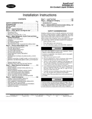
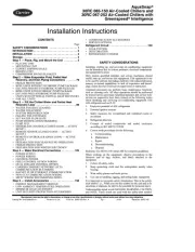
Installation Instructions
CONTENTS
Page
SAFETY CONSIDERATIONS . . . . . . . . . . . . . . . . . . . 1
INTRODUCTION . . . . . . . . . . . . . . . . . . . . . . . . . . . . . . 3
INSTALLATION . . . . . . . . . . . . . . . . . . . . . . . . . . . . . . 3
Storage . . . . . . . . . . . . . . . . . . . . . . . . . . . . . . . . . . . . . 3
Step 1 — Place, Rig, and Mount the Unit . . . . . . . . . 3
•PLACING UNIT
MOUNTING UNIT
EXPORT SHIPPING RAILS
RIGGING UNIT
COMPRESSOR SOUND BLANKETS
Step 2 — Make Evaporator Fluid, Partial Heat
Recovery, and Drain Piping Connections . . . . . . . 79
FREEZE PROTECTION
BPHE UNITS WITHOUT HYDRONIC PUMP PACKAGE
DX UNITS WITHOUT HYDRONIC PUMP PACKAGE
BPHE UNITS WITH HYDRONIC PUMP PACKAGE
DX UNITS WITH HYDRONIC PUMP PACKAGE
UNITS WITH OPTIONAL PARTIAL HEAT RECOVERY
FOR ALL UNITS
Step 3 — Fill the Chilled Water and Partial Heat
Recovery Loop . . . . . . . . . . . . . . . . . . . . . . . . . . . 89
WATER SYSTEM CLEANING
WATER TREATMENT
SYSTEM PRESSURIZATION
FILLING THE SYSTEM(S)
SET WATER FLOW RATE
PUMP MODIFICATION/TRIMMING
•PUMP VFD
SENSORLESS CONTROL (CLOSED LOOP) — ACTIVE
SETUP 1
REMOTE SENSOR (CLOSED LOOP) — ACTIVE
SETUP 2
REMOTE CONTROLLER (OPEN LOOP) — ACTIVE
SETUP 3
PREPARATION FOR YEAR ROUND OPERATION
FREEZE PROTECTION
PREPARATION FOR WINTER SHUTDOWN
Step 4 — Make Electrical Connections . . . . . . . . . 105
POWER SUPPLY
•POWER WIRING
CONTROL POWER
FIELD CONTROL OPTION WIRING
DUAL CHILLER CONTROL OPTION
CARRIER COMFORT NETWORK
®
(CCN)
COMMUNICATION BUS WIRING
BACNET IP OR ETHERNET COMMUNICATION
NON-CCN COMMUNICATION WIRING
MS/TP WIRING RECOMMENDATIONS
Step 5 — Install Accessories . . . . . . . . . . . . . . . . . 158
ENERGY MANAGEMENT MODULE
LOW AMBIENT TEMPERATURE OPERATION
MINIMUM LOAD ACCESSORY
UNIT SECURITY/PROTECTION ACCESSORIES
COMMUNICATION ACCESSORIES
SERVICE OPTIONS
Refrigerant Circuit . . . . . . . . . . . . . . . . . . . . . . . . . .159
LEAK TESTING
DEHYDRATION
REFRIGERANT CHARGE
SAFETY CONSIDERATIONS
Installing, starting up, and servicing air-conditioning equipment
can be hazardous due to system pressures, electrical components,
and equipment location.
Only trained, qualified installers and service mechanics should
install, start up, and service this equipment. This equipment is not
to be used by persons (including children) with reduced physical,
sensory or mental capabilities, or lack of experience and knowl-
edge, unless they have been given supervision or instruction.
Untrained personnel can perform basic maintenance functions,
such as cleaning coils. All other operations should be performed
by trained service personnel. Qualified installers and service tech-
nicians are required to have been trained on the following topics
when installing and servicing air-conditioning equipment with
A2L refrigerant such as R-32:
1. Explosive potential of A2L refrigerants
2. Potential ignition sources
3. Safety measures for unventilated and ventilated rooms or
enclosures
4. Refrigerant detectors
5. Concept of sealed components and sealed enclosures
according to IEC 60079-15:2010
6. Correct work procedures for the following:
a. Commissioning
b. Maintenance
c. Repair
d. Decommissioning
e. Disposal
Reference UL 60335-2-40 Annex HH for complete guidelines.
When working on the equipment, observe precautions in the
literature and on tags, stickers, and labels attached to the
equipment.
1. Follow all safety codes.
2. Keep quenching cloth and fire extinguisher nearby when
brazing.
3. Wear safety glasses and work gloves.
4. Use care in handling, rigging, and setting bulky equipment.
It is important to recognize safety information. This is the safety-
alert symbol . When you see this symbol on the unit and in in-
structions or manuals, be alert to the potential for personal injury.
Understand the signal words DANGER, WARNING, CAUTION,
and NOTE. These words are used with the safety-alert symbol.
AquaSnap
®
30RC 065-150 Air-Cooled Chillers and
30RC 067-252 Air-Cooled Chillers with
Greenspeed
®
Intelligence
2
DANGER identifies the most serious hazards which will result in
severe personal injury or death. WARNING signifies hazards
which could result in personal injury or death. CAUTION is used
to identify unsafe practices, which may result in minor personal
injury or product and property damage. NOTE is used to highlight
suggestions which will result in enhanced installation, reliability,
or operation.
NOTE: Take notice of the following symbols, which are required
for A2L refrigerants and can be found on the unit:
SYMBOL CODE MEANING
IEC 60417-5032 (2002-10) Alternating current
IEC 60417-5019 (2006-8) Protective earth
IEC 60417-5018 (2006-10) Functional earthing
ISO 7000-0434A (2004-01) Caution
ISO 7000-0790 (2004-01)
Read operator’s
manual
IEC 60417-5036 (2002-10) Dangerous voltage
GHS02: Flammable Flammable gas
ISO 7010-W021 (2011-05)
Warning: flammable
materials
ISO 7000-1659 (2004-01)
Service indicator:
read technical
manual
ISO 7000-1701 (2004-01) Pressure
ISO 7000-1641 (2004-01)
Operator’s manual:
operating
instructions
WARNING
Electrical shock can cause personal injury and death. Shut off
all power to this equipment during installation. There may be
more than one disconnect switch. Tag all disconnect locations
to alert others not to restore power until work is completed.
IMPORTANT: This equipment generates, uses, and can radiate
radio frequency energy and, if not installed and used in
accordance with these instructions, may cause radio interference.
It has been tested and found to comply with the limits of a Class
A computing device pursuant to International Standard in North
America EN 61000-2/3, which are designed to provide
reasonable protection against such interference when operated in
a commercial environment.
CAUTION
This system uses either Puron
®
refrigerant (R-410A) or an
A2L refrigerant (R-32), both of which have higher pressures
than R-22 and other refrigerants. No other refrigerant can be
used in this system. Failure to use gauge set, hoses, and
recovery systems designed to handle Puron refrigerant
(R-410A) or R-32 may result in equipment damage or personal
injury. Reference UL 60335-2-40 Annex DD for guidelines on
proper A2L refrigerant handling and equipment used for A2L
refrigerant. If unsure about equipment, consult the equipment
manufacturer.
WARNING
DO NOT USE TORCH to remove any component. System
contains oil and refrigerant under pressure.
To remove a component, wear protective gloves and goggles
and proceed as follows:
a. Shut off electrical power to unit.
b. Recover refrigerant to relieve all pressure from sys-
tem using both high-pressure and low pressure ports.
c. Traces of vapor should be displaced with nitrogen
and the work area should be well ventilated. Refrig-
erant in contact with an open flame produces toxic
gases.
d. Cut component connection tubing with tubing cutter
and remove component from unit. Use a pan to catch
any oil that may come out of the lines and as a gauge
for how much oil to add to the system.
e. Carefully unsweat remaining tubing stubs when nec-
essary. Oil can ignite when exposed to torch flame.
Failure to follow these procedures may result in personal
injury or death.
CAUTION
DO NOT re-use compressor oil or any oil that has been
exposed to the atmosphere. Dispose of oil per local codes and
regulations. DO NOT leave refrigerant system open to air any
longer than the actual time required to service the equipment.
Seal circuits being serviced and charge with dry nitrogen to
prevent oil contamination when timely repairs cannot be
completed. Failure to follow these procedures may result in
damage to equipment.
WARNING
This product can expose you to chemicals including lead and
lead components, which are known to the State of California
to cause cancer and birth defects or other reproductive harm.
For more information, go to www.P65Warnings.ca.gov.
WARNING
DO NOT use means to accelerate the defrosting process, or to
clean, other than those recommended by the manufacturer.
If unit is to be stored, it shall be stored in an area or room
without continuously operating open flames (for example, an
operating gas appliance) or other potential ignition sources,
such as operating electric heaters or hot surfaces.
Do not pierce or burn.
Be aware that refrigerants may not contain an odor.
3
INTRODUCTION
These instructions cover installation of 30RC 065-150 and
30RC 067-252 air-cooled liquid chillers with electronic controls
and units with factory-installed options (FIOPs). See Fig. 1 for
model number nomenclature.
NOTE: The 30RC 065-150 and 30RC 067-252 air-cooled chillers
with Greenspeed
®
technology include high-efficiency variable
speed condenser fans. (See Fig. 1.)
INSTALLATION
Storage
If the unit is to be stored for a period of time before installation or
start-up, be sure to protect the machine from construction dirt and
moisture. Keep protective shipping covers in place until machine
is ready for installation.
Step 1 — Place, Rig, and Mount the Unit
NOTE: Inspect the unit upon arrival for damage. If damage is
found, file a claim right away with the shipping company.
PLACING UNIT
When considering location for the unit, be sure to consult National
Electrical Code (NEC, U.S.A.) and local code requirements.
Allow sufficient space for airflow, wiring, piping, and service.
(See Fig. 2-43.) Be sure surface beneath the unit is level and is ca-
pable of supporting the operating weight of the unit. See Fig. 44
and Tables 1-10 for unit lifting points and mounting and operating
weights.
Locate the unit so that the condenser airflow is unrestricted both
above and on the sides of the unit. Airflow and service clearances
are 6 ft (1.8 m) around the unit. Acceptable clearance on the
evaporator connection side or end opposite the control box unit
can be reduced to 3 ft (1 m) without sacrificing performance as
long as the remaining three sides are unrestricted. Acceptable
clearance on the side with a control box can be reduced to 4 ft
(1.3 m), due to NEC regulations, without sacrificing performance
as long as the remaining three sides are unrestricted. Provide
ample room for servicing and removing evaporator. See Fig. 6-43
for required clearances. Local codes for clearances take prece-
dence over the manufacturer’s recommendations when local codes
call for greater clearances.
If multiple units are installed at the same site, a separation of 10 ft
(3 m) between the sides of the machines is required to maintain
proper airflow and minimize the chances of condenser air
recirculation.
MOUNTING UNIT
The unit may be mounted on a level pad directly on the base rails,
on rails along the long axis of the machine, or on vibration isola-
tion springs. (See Fig. 47.) For all units, ensure placement area is
strong enough to support unit operating weight. (See Tables 1-3
and Fig. 44.) Mounting holes are provided for securing the unit to
the pad, mounting rail, or vibration isolation springs. The base rail
is made from steel; see Fig. 45 for base rail shape. See Fig. 6-43
for locations of mounting points. At the mounting points, a
U-shaped channel is welded into the base rail to provide a flat
plate for mounting. See Fig. 46 for mounting plate dimensions.
The 1.46 in. (37 mm) dimension shown is from the outside edge
of the rail to the mounting hole.
NOTE: The 1.46 in. (37 mm) dimension in Fig. 46 is not the same
dimension as the 1.48 in. (37.5 mm) flange that is turned under the
base rail in Fig. 45.
Bolt the unit securely to pad or rails. If vibration isolators (field-
supplied, see Fig. 47) are required for a particular installation, see
unit weight distribution in Fig. 44 to aid in the proper selection of
isolators. Once installed, the unit must be level to within 1/8 in.
per ft (1 cm per meter) along the long axis of the unit. This is re-
quired for oil return to the compressor(s). For more details about
physical data, see Tables 4-9.
NOTE: For units that are point loaded, such as those using rubber
and shear isolators, the mounting pocket in the base rail must be
supported. If the isolator includes a plate that spans across the
mounting pocket, no further support is needed. If the isolator is
point loaded, add a backup plate to the mounting plate 1/4 in.
thick x 6 in. wide x 8 in. long, centered on the unit mounting plate.
WARNING
UNIT MUST NOT BE ACCESSIBLE TO THE GENERAL
PUBLIC.
WARNING
Place and mount units in accordance to ASHRAE 15
guidelines. Units located outside a building and within 20 ft
(6.1 m) of any building opening shall be governed by the
occupancy classification of the building. The foundation and
mounting structure for the unit shall be of non-combustible
construction.

Produkspesifikasjoner

Merke: Carrier
Kategori: luftkondisjonering
Modell: AquaSnap 30RC

Trenger du hjelp?

Hvis du trenger hjelp med Carrier AquaSnap 30RC still et spørsmål nedenfor, og andre brukere vil svare deg


luftkondisjonering Carrier Manualer

luftkondisjonering Manualer

Nyeste luftkondisjonering Manualer