Carrier Aquaforce 30XA Bruksanvisning
Carrier
luftkondisjonering
Aquaforce 30XA
Les nedenfor 📖 manual på norsk for Carrier Aquaforce 30XA (140 sider) i kategorien luftkondisjonering. Denne guiden var nyttig for 2 personer og ble vurdert med 4.5 stjerner i gjennomsnitt av 2 brukere
Side 1/140

Manufacturer reserves the right to discontinue, or change at any time, specifications or designs without notice and without incurring obligations.
Catalog No. 04-53300202-01 Printed in U.S.A. Form 30XA-27SI Pg 1 9-21 Replaces: 30XA-26SI
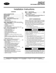
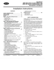
Installation Instructions
CONTENTS
Page
SAFETY CONSIDERATIONS . . . . . . . . . . . . . . . . . . . 1
INTRODUCTION . . . . . . . . . . . . . . . . . . . . . . . . . . . . . . 2
INSTALLATION . . . . . . . . . . . . . . . . . . . . . . . . . . . . . . 2
Storage . . . . . . . . . . . . . . . . . . . . . . . . . . . . . . . . . . . . . 2
Step 1 — Inspect Shipment . . . . . . . . . . . . . . . . . . . . 2
Step 2 — Place, Mount, and Rig the Unit . . . . . . . . . 2
• PL
ACING UNIT
• MOUNTING UNIT
• RIGGING UNIT (SEE FIG. 27-29)
Step 3 — Make Refrigerant, Cooler Fluid and Drain
Piping Connections . . . . . . . . . . . . . . . . . . . . . . . 88
• 30XA501 UNIT ASSEMBLY
• GENERAL
• FLOODED COOLER UNITS
• DX COOLER UNITS
• PREPARATION FOR YEAR-ROUND OPERATION
Step 4 — Fill the Chilled Water Loop . . . . . . . . . . 108
• WATER SYSTEM CLEANING
• WATER TREATMENT
• SYSTEM PRESSURIZATION
• FILLING THE SYSTEM
• SET WATER FLOW RATE
• PUMP MODIFICATION/TRIMMING
• PUMP VFD
• SENSORLESS CONTROL (CLOSED LOOP), ACTIVE
SETUP 1
• REMOTE SENSOR (CLOSED LOOP), ACTIVE SETUP 2
• REMOTE CONTROLLER (OPEN LOOP), ACTIVE SETUP
3
• FREEZE PROTECTION
• PREPARATION FOR WINTER SHUTDOWN
Step 5 — Make Electrical Connections . . . . . . . . . 113
• POWER SUPPLY
• FIELD POWER CONNECTIONS (SEE FIG. 61)
• POWER WIRING
• FIELD CONTROL POWER CONNECTIONS
• CCN COMMUNICATION BUS WIRING
• NON-CCN COMMUNICATION WIRING
• FIELD CONTROL OPTION WIRING
• DUAL CHILLER LEAVING WATER SENSOR
Step 6 — Install Accessories . . . . . . . . . . . . . . . . . 136
• ENERGY MANAGEMENT MODULE
• REMOTE ENHANCED DISPLAY
• LOW AMBIENT TEMPERATURE OPERATION
• MINIMUM LOAD ACCESSORY
• UNIT SECURITY/PROTECTION ACCESSORIES
• COMMUNICATION ACCESSORIES
• SERVICE OPTIONS
Step 7 — Leak Test Unit . . . . . . . . . . . . . . . . . . . . .136
St
ep 8 — Refrigerant Charging . . . . . . . . . . . . . . . .136
• DEHYDRATION
• REFRIGERANT CHARGE
Step 9 — Optional BACnet Communication Wiring .137
• MS/TP WIRING RECOMMENDATIONS
SAFETY CONSIDERATIONS
Installing, starting up, and servicing this equipment can be hazard-
ous due to system pressures, electrical components, and equip-
ment location. Only trained, qualified installers and service me-
chanics should install, start up, and service this equipment.
When working on the equipment, observe precautions in the liter-
ature, and on tags, stickers, and labels attached to the equipment.
• Follow all safety codes.
• Wear safety glasses and work gloves.
• Use care in handling, rigging, and setting bulky equipment.
WARNING
DO NOT USE TORCH to remove any component. System
contains oil and refrigerant under pressure.
To remove a component, wear protective gloves and goggles
and proceed as follows:
a. Shut off electrical power to unit.
b. Recover refrigerant to relieve all pressure from system
using both high-pressure and low pressure ports.
c. Traces of vapor should be displaced with nitrogen and
the work area should be well ventilated. Refrigerant in
contact with an open flame produces toxic gases.
d. Cut component connection tubing with tubing cutter and
remove component from unit. Use a pan to catch any oil
that may come out of the lines and as a gage for how
much oil to add to the system.
e. Carefully un-sweat remaining tubing stubs when neces-
sary. Oil can ignite when exposed to torch flame.
Failure to follow these procedures may result in personal inju-
ry or death.
WARNING
Electrical shock can cause personal injury and death. Shut off
all power to this equipment during installation. There may be
more than one disconnect switch. Tag all disconnect locations
to alert others not to restore power until work is completed.
AquaForce
®
30XA080-501
Air-Cooled Liquid Chillers

2
INTRODUCTION
These instructions cover installation of 30XA080-501 air-
cooled liquid chillers with electronic controls and units with
factory-installed options (FIOPs). See Fig. 1.
INSTALLATION
Storage
If the unit is to be stored for a period of time before installation or
start-up, be sure to protect the machine from construction dirt.
Keep protective shipping covers in place until the machine is
ready for installation.
Step 1 — Inspect Shipment
Inspect unit for damage upon arrival. If damage is found, immedi-
ately file a claim with the shipping company, and contact your lo-
cal Carrier representative.
Step 2 — Place, Mount, and Rig the Unit
When considering a location for the unit, be sure to consult NEC
(National Electrical Code, U.S.A.) and/or local code requirements.
Allow sufficient space for airflow, wiring, piping, and service. See
Fig. 2-23.
NOTE: To facilitate refrigerant vent piping, all units have fusible
plugs with 1/4 in. SAE (Society of Automotive Engineers) flares
and pressure reliefs with 3/4 in. NPT fittings (if required by local
codes).
NOTE: The 30XA501 units are shipped as two separate pieces re-
ferred to as the 501A module (section including cooler and com-
pressors), referred to on the unit nameplate as 30XAB50A, and
the 501B module, referred to on the unit nameplate as
30XAB50B. These two pieces must be field combined prior to in-
stalling cooler piping and electrical connections (see the section
30XA501 Unit Assembly on page 88).
PLACING UNIT
Locate the unit so that the condenser airflow is unrestricted
both above and on the sides of the unit. Airflow and service
clearances are 6 ft (1.8 m) around the unit. Acceptable clear-
ance on the sides or ends without control boxes can be reduced
to 3 ft (1 m) without sacrificing performance as long as the re-
maining three sides are unrestricted. Acceptable clearance on
the side with a control box can be reduced to 4 ft (1.3 m) due to
NEC regulations, without sacrificing performance as long as
the remaining three sides are unrestricted. Provide ample room
for servicing and removing the cooler. See Fig. 2-23 for re-
quired clearances. Local codes for clearances take precedence
over the manufacturer’s recommendations when local codes
call for greater clearances. Units are suitable for outdoor use
only.
If multiple units are installed at the same site, a minimum separa-
tion of 10 ft (3 m) between the sides of the machines is required to
maintain proper airflow and minimize the chances of condenser
air recirculation.
MOUNTING UNIT
The unit may be mounted on a level pad directly on the base rails,
on a raised mounting rail around the unit, or on vibration isolation
springs. For all units, ensure placement area is strong enough to
support unit operating weight. See Tables 1-8. Mounting holes are
provided for securing the unit to the pad, mounting rail or vibra-
tion isolation springs. Bolt the unit securely to pad or rails. If vi-
bration isolators (field-supplied) are required for a particular in-
stallation, refer to unit weight distribution in Fig. 24-26 to aid in
the proper selection of isolators. The 30XA units can be mounted
directly on spring isolators. Once installed, the unit must be level
to within 1/8-in. per ft (1 cm per meter) along the long axis of the
oil separator. This is required for oil return to the compressor(s).
CAUTION
DO NOT re-use compressor oil or any oil that has been ex-
posed to the atmosphere. Dispose of oil per local codes and
regulations. DO NOT leave refrigerant system open to air any
longer than the actual time required to service the equipment.
Seal circuits being serviced and charge with dry nitrogen to
prevent oil contamination when timely repairs cannot be com-
pleted. Failure to follow these procedures may result in dam-
age to equipment.
IMPORTANT: This equipment generates, uses, and can radiate
radio frequency energy and if not installed and used in accor-
dance with these instructions may cause radio interference. It has
been tested and found to comply with the limits of a Class A
computing device as defined by FCC (Federal Communications
Commission, U.S.A.) regulations, Subpart J of Part 15, which
are designed to provide reasonable protection against such inter-
ference when operated in a commercial environment.

3
Fig. 1 — AquaForce
®
Chiller Model Number Designation
30XA – AquaForce® Air-Cooled Chiller
Design Series
Voltage
1 – 575-3-60
2 – 380-3-60
4 – 230-3-60
Condenser Coil/Ambient/Low Sound Options
- – Aluminum Fin/Copper Tube, High Ambient Temperature
0 – Copper Fin/Copper Tube, High Ambient Temperature
1 – Aluminum Pre-Coat Fin/Copper Tube, High Ambient Temperature
2 – Aluminum E-Coat Fin/Copper Tube, High Ambient Temperature
3 – Copper E-Coat Fin/Copper Tube, High Ambient Temperature
4 – Novation® Heat Exchanger (MCHX), High Ambient
Temperature
5 – MCHX E-Coat, High Ambient Temperature
6 – Aluminum Fin/Copper Tube, High Ambient Temperature,
Low Sound
7 – Copper Fin/Copper Tube, High Ambient Temperature, Low Sound
8 – Aluminum Pre-Coat Fin/Copper Tube, High Ambient Temperature,
Low Sound
9 – Aluminum E-Coat Fin/Copper Tube, High Ambient Temperature,
Low Sound
B – Copper E-Coat Fin/Copper Tube, High Ambient Temperature,
Low Sound
C – MCHX, High Ambient Temperature, Low Sound
D – MCHX E-Coat, High Ambient Temperature, Low Sound
F – Aluminum Fin/Copper Tube, Standard Ambient Temperature,
Low Sound
G – Copper Fin/Copper Tube, Standard Ambient Temperature,
Low Sound
H – Aluminum Pre-Coat Fin/Copper Tube, Standard Ambient
Temperature, Low Sound
J – Aluminum E-Coated Fin/Copper Tube, Standard Ambient
Temperature, Low Sound
K – Copper E-Coat Fin/Copper Tube, Standard Ambient Temperature,
Low Sound
L – MCHX, Standard Ambient Temperature, Low Sound
M – MCHX E-Coat, Standard Ambient Temperature, Low Sound
N – Aluminum Fin/Copper Tube, Standard Ambient Temperature
P – Copper Fin/Copper Tube, Standard Ambient Temperature
Q – Aluminum Pre-Coat Fin/Copper Tube, Standard Ambient
Temperature
R – Aluminum E-Coat Fin/Copper Tube, Standard Ambient
Temperature
S – Copper E-Coat Fin/Copper Tube, Standard Ambient Temperature
T – MCHX, Standard Ambient Temperature
V – MCHX E-Coat, Standard Ambient Temperature
Cooler Options
- – Integral DX Cooler without Heater
0 – Integral Cooler with Heater†
1 – Integral DX Cooler with Heater, Hydronic Package
3 – Integral Flooded Cooler with Heater, Minus One Pass
5 – Integral Flooded Cooler with Heater, Plus One Pass
6 – Integral DX Cooler without Heater, Hydronic Package
7 – Integral Cooler with Heater, Full End Screen, Coil Trim Panels, Grilles†
8 – Integral DX Cooler with Heater, Hydronic Package, Full End Screen,
Coil Trim Panels, Grilles
F
– Integral DX Cooler without Heater, Hydronic Package, Full End Screen,
Coil Trim Panels, Grilles
G
– Integral DX Cooler without Heater, Full End Screen, Coil Trim Panels, Grilles
K – Integral Flooded Cooler with Heater, Minus One Pass, Full End Screen,
Coil Trim Panels, Grilles
M – Integral Flooded Cooler with Heater, Plus One Pass, Full End Screen,
Coil Trim Panels, Grilles
Packaging/Security Options
0 – Coil Face Shipping Protection (CFSP), Skid
1 – CFSP, Skid, Top Crate, Bag
3 – CFSP, Coil Trim Panels
4 – CFSP, Skid, Coil Trim Panels
5 – CFSP, Skid, Top Crate, B
ag, Coil Trim Panels
7 – CFSP, Coil Trim Panels, Upper and Lower Grilles
8 – CFSP, Skid, Coil Trim Panels, Upper and Lower Grilles
9 – CFSP, Skid, Top Crate, Bag, Coil Trim Panels, Upper and Lower Grilles
C – CFSP, Coil Trim Panels, Upper and Lower Grilles, Upper Hail Guards
D – CFSP, Skid, Coil Trim Panels, Upper and Lower Grilles, Upper Hail Guards
F – CFSP, Skid, Top Crate, Bag, Coil Trim Panels, Upper and Lower Grilles,
Upper Hail Guards
H – CFSP, Skid, High SCCR
J – CFSP, Skid, Top Crate, Bag, High SCCR
K – CFSP, High SCCR
L – CFSP
M – CFSP, Coil Trim Panels, High SCCR
N – CFSP, Skid, Coil Trim Panels, High SCCR
P – CFSP, Skid, Top Crate, Bag, Coil Trim Panels, High SCCR
R – CFSP, Coil Trim Panels, Upper and Lower Grilles, High SCCR
S – CFSP, Skid, Coil Trim Panels, Upper and Lower Grilles, High SCCR
T – CFSP, Skid, Top Crate, Bag, Coil Trim Panels, Upper and Lower Grilles,
High SCCR
W – CFSP, Coil Trim Panels, Upper and Lower Grilles, Upper Hail Guards, High SCCR
X – CFSP, Skid, Coil Trim Panels, Upper and Lower Grilles, Upper Hail Guards,
High SCCR
Y – CFSP, Skid, Top Crate, Bag, Coil Trim Panels, Upper and Lower Grilles, Upper
Hail Guards, High SCCR
Controls/Communication Options
- – Navigator™ Display
0 – Navigator Display, EMM
1 – Navigator Display, Service Option
2 – Navigator Display, EMM, Service Option
3 – Touch Pilot™ Display
4 – Touch Pilot Display, EMM
5 – Touch Pilot Display, Service Option
6 – Touch Pilot Display, EMM, Service Option
7 – Navigator Display, BACnet Translator
8 – Navigator Display, BACnet Translator, EMM
9 – Navigator Display, BACnet Translator, Service Option
B – Navigator Display, BACnet Translator, EMM, Service Option
C – Touch Pilot Display, BACnet Translator
D – Touch Pilot Display, BACnet Translator, EMM
F – Touch Pilot Display, BACnet Translator, Service Option
G – Touch Pilot Display, BACnet Translator, EMM, Service Option
H
– Navigator Display, LON Translator
J
– Navigator Display, LON Translator, EMM
K – Navigator Display, LON Translator, Service Option
L – Navigator Display, LON Translator, EMM, Service Option
M – Touch Pilot Display, LON Translator
N – Touch Pilot Display, LON Translator, EMM
P – Touch Pilot Display, LON Translator, Service Option
Q – Touch Pilot Display, LON Translator, EMM, Service Option
R – Navigator Display, BACnet Communication
S – Navigator Display, BACnet Communication, EMM
T – Navigator Display, BACnet Communication, Service Option
V – Navigator Display, BACnet Communication, EMM, Service Option
W – Touch Pilot Display, BACnet Communication
X – Touch Pilot Display, BACnet Communication, EMM
Y – Touch Pilot Display, BACnet Communication, Service Option
Z – Touch Pilot Display, BACnet Communication, EMM, Service Option
Electrical Options
- – Single Point Power, XL, Terminal Block, No Control Transformer
0 – Single Point Power, Wye-Delta, Terminal Block, No Control Transformer
3 – Dual Point Power, XL, Terminal Block, No Control Transformer
4 – Dual Point Power, Wye-Delta, Terminal Block, No Control Transformer
7 – Single Point Power, XL, Disconnect, No Control Transformer
8 – Single Point Power, Wye-Delta, Disconnect, No Control Transformer
C – Dual Point Power, XL, Disconnect, No Control Transformer
D – Dual Point Power, Wye-Delta, Disconnect, No Control Transformer
H – Single Point Power, XL, Terminal Block, Control Transformer
J – Single Point Power, Wye-Delta, Terminal Block, Control Transformer
M – Dual Point Power, XL, Terminal Block, Control Transformer
N – Dual Point Power, Wye-Delta, Terminal Block, Control Transformer
R – Single Point Power, XL, Disconnect, Control Transformer
S – Single Point Power, Wye-Delta, Disconnect, Control Transformer
W – Dual Point Power, XL, Disconnect, Control Transformer
X – Dual Point Power, Wye-Delta, Disconnect, Control Transformer
Refrigeration Circuit Options
- – None
0 – Suction Line Insulation
1 – Isolation Valves
2 – Low Ambient Head Pressure Control
3 – Suction Line Insulation, Isolation Valves
4 – Suction Line Insulation, Low Ambient Head Pressure Control
5 – Isolation Valves, Low Ambient Head Pressure Control
6 – Suction Line Insulation, Isolation Valves, Head Pressure Control
7 – Minimum Load Control
8 – Suction Line Insulation, Minimum Load Control
9 – Isolation Valves, Minimum Load Control
B – Low Ambient Head Pressure Control Operation, Minimum Load Control
C – Suction Line Insulation, Isolation Valves, Minimum Load Control
D – Suction Line Insulation, Head Pressure Control, Minimum Load Control
F – Isolation Valves, Head Pressure Control, Minimum Load Control
G
– Suction Line Insulation, Isolation Valves, Head Pressure Control, Minimum Load Control
Hydronic Pump Package Options
- – None
1 – Single Pump, 5 HP
2 – Single Pump, 7.5 HP
3 – Single Pump, 10 HP
4 – Single Pump, 15 HP
7 – Dual Pump, 5 HP
8 – Dual Pump, 7.5 HP
B – Dual Pump, 10 HP
C – Dual Pump, 15 HP
6 – 460-3-60
7 – 200-3-60
G
– Single Pump, 5 HP with VFD
H
– Single Pump, 7.5 HP with VFD
J – Single Pump, 10 HP with VFD
K – Single Pump, 15 HP with VFD
N – Dual Pump, 5 HP with VFD
P – Dual Pump, 7.5 HP with VFD
Q – Dual Pump, 10 HP with VFD
R – Dual Pump, 15 HP with VFD
A
Unit Sizes*
080 102 140 182 240 282 350 451
082 110 142 200 242 300 352 476
090 112 160 202 260 302 400 500
092 120 162 220 262 325 401 501
100 122 180 222 280 327 450
LEGEND
* xx0, xx1, xx5, and xx6 size units contain flooded style coolers. Unit
size 501 ships in two pieces: 501A (unit nameplate 50A) and 501B
(unit nameplate 50B)
xx2 and xx7 size units contain direct expansion (DX) style coolers.
† Both flooded and DX cooler.
CFSP — Face Shipping Protection
EMM — Energy Management Module
LON — Local Operating Network
SCCR — Short Circuit Current Rating
XL — Across-the-Line Starter
Produkspesifikasjoner
Merke: | Carrier |
Kategori: | luftkondisjonering |
Modell: | Aquaforce 30XA |
Trenger du hjelp?
Hvis du trenger hjelp med Carrier Aquaforce 30XA still et spørsmål nedenfor, og andre brukere vil svare deg
luftkondisjonering Carrier Manualer
25 August 2025
25 August 2025
25 August 2025
25 August 2025
25 August 2025
25 August 2025
25 August 2025
25 August 2025
25 August 2025
25 August 2025
luftkondisjonering Manualer
- luftkondisjonering MSW
- luftkondisjonering Haier
- luftkondisjonering LG
- luftkondisjonering BEKO
- luftkondisjonering Exquisit
- luftkondisjonering Danby
- luftkondisjonering Gree
- luftkondisjonering TCL
- luftkondisjonering Nabo
- luftkondisjonering AEG
- luftkondisjonering Cecotec
- luftkondisjonering Samsung
- luftkondisjonering Delonghi
- luftkondisjonering Kogan
- luftkondisjonering Midea
- luftkondisjonering Gorenje
- luftkondisjonering Panasonic
- luftkondisjonering Olimpia Splendid
- luftkondisjonering Sencor
- luftkondisjonering Frigidaire
- luftkondisjonering Dimplex
- luftkondisjonering Hitachi
- luftkondisjonering Tripp Lite
- luftkondisjonering Ufesa
- luftkondisjonering Master
- luftkondisjonering Einhell
- luftkondisjonering Mitsubishi
- luftkondisjonering Philco
- luftkondisjonering Klarstein
- luftkondisjonering Wilfa
- luftkondisjonering Heinner
- luftkondisjonering Argoclima
- luftkondisjonering Primo
- luftkondisjonering Broan
- luftkondisjonering Eurom
- luftkondisjonering Honeywell
- luftkondisjonering Crosley
- luftkondisjonering Premium Levella
- luftkondisjonering Sonnenkonig
- luftkondisjonering Orima
- luftkondisjonering Qlima
- luftkondisjonering Dantherm
- luftkondisjonering Ariston Thermo
- luftkondisjonering Trotec
- luftkondisjonering Berner
- luftkondisjonering Ivation
Nyeste luftkondisjonering Manualer
25 August 2025
25 August 2025
25 August 2025
25 August 2025
25 August 2025
25 August 2025
25 August 2025
25 August 2025
25 August 2025
25 August 2025