Randell 3500 Bruksanvisning
Randell
Ikke kategorisert
3500
Les nedenfor 📖 manual på norsk for Randell 3500 (15 sider) i kategorien Ikke kategorisert. Denne guiden var nyttig for 17 personer og ble vurdert med 4.5 stjerner i gjennomsnitt av 9 brukere
Side 1/15
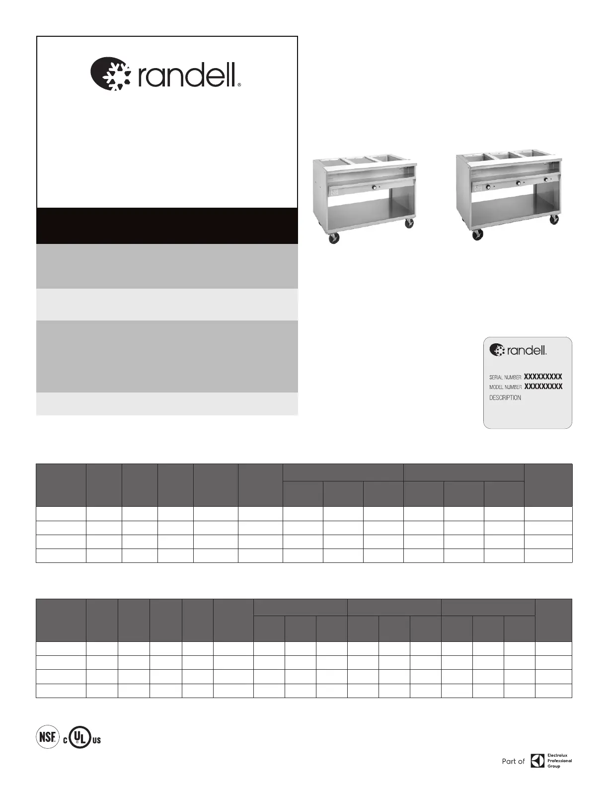
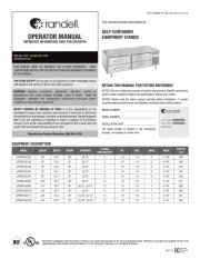
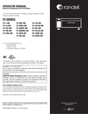
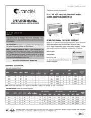
OPERATOR MANUAL
IMPORTANT INFORMATION, KEEP FOR OPERATOR
PART NUMBER PP MNL0027, Rev E (06/25)
This manual provides information for:
ELECTRIC HOT FOOD HOLDING UNIT MODEL
SERIES 3300/3500/3600/HT-EHI
RETAIN THIS MANUAL FOR FUTURE REFERENCE
NOTICE: Due to a continuous program of product improvement, Randell reserves the
right to make changes in design and specifications without prior notice.
NOTICE: Please read the entire manual carefully before installation. If certain
recommended procedures are not followed, warranty claims will be denied.
MODEL NUMBER _________________________
SERIAL NUMBER _________________________
INSTALLATION DATE ______________________
The serial number is located on the control panel. An
example is shown here.
EQUIPMENT DESCRIPTION
3300 SERIES COMMON WATERBATH
MODEL LENGTH DEPTH HEIGHT
#
WELLS
#
ELEMENTS
208V 240V
SHIP WT
(LBS)
KW AMPS NEMA KW AMPS NEMA
3312 33” 30” 36” 2 1 3
14.4
6-20P 3 12.5 6-20P 116
3313 48” 30” 36” 3 1 3 14.4 6-20P 3 12.5 6-20P 174
3314 63” 30” 36” 4 2 6 28.8 6-50P 6 25 6-50P 232
3315 78” 30” 36” 5 2 6 28.8 6-50P 6 25 6-50P 290
NOTE: All 3300 series units require 1” to 2” of water be added PRIOR to heating of the elements. Hot water is recommended.
3500 SERIES OPEN WELL (spillage pans required for wet operation)
MODEL LENGTH DEPTH HEIGHT
#
WELLS
#
ELEMENTS
120V – 750 WATT 208V – 865 WATT 240V – 1150 WATT
SHIP WT
(LBS)
KW AMPS NEMA KW AMPS NEMA KW AMPS NEMA
3512 33” 30” 36” 2 2 1.5
12.5
5-20P 1.73 8.32 6-15P 2.3 9.58 6-15P 116
3513 48” 30” 36” 3 3 2.25 18.75 5-30P 2.6 12.48 6-20P 3.45 14.37 6-20P 174
3514 63” 30” 36” 4 4 3 25 5-50P 3.46 16.64 6-30P 4.6 19.16 6-30P 232
3515 78” 30” 36” 5 5 3.75 31.25 5-50P 4.33 20.8 6-30P 5.75 23.95 6-30P 290
Information contained in this document is known to be current and accurate at the time of printing/creation. Reference our product line website for the most updated
product information and specifications. © 2025 Electrolux Professional, Inc. All Rights Reserved.
888-994-7636, fax 888-864-7636
randell.com
THIS MANUAL MUST BE RETAINED FOR FUTURE REFERENCE. READ,
UNDERSTAND AND FOLLOW THE INSTRUCTIONS AND WARNINGS CONTAINED
IN THIS MANUAL.
FOR YOUR SAFETY Do not store or use gasoline or other flammable vapors
and liquids in the vicinity of this or any other appliance.
NOTIFY CARRIER OF DAMAGE AT ONCE It is the responsibility of the
consignee to inspect the container upon receipt of same and to determine
the possibility of any damage, including concealed damage. Randell suggests
that if you are suspicious of damage to make a notation on the delivery
receipt. It will be the responsibility of the consignee to file a claim with the
carrier. We recommend that you do so at once.
Manufacture Service/Questions 888-994-7636.
3313 shown
3613 shown
Produkspesifikasjoner
| Merke: | Randell |
| Kategori: | Ikke kategorisert |
| Modell: | 3500 |
Trenger du hjelp?
Hvis du trenger hjelp med Randell 3500 still et spørsmål nedenfor, og andre brukere vil svare deg
Ikke kategorisert Randell Manualer

22 September 2025
21 September 2025

20 September 2025

20 September 2025
20 September 2025

20 September 2025
20 September 2025
Ikke kategorisert Manualer
- Seaward
- Atlas Sound
- American Audio
- GARDE
- Singercon
- Pluto
- Vivanco
- Sure Petcare
- Deaf Bonce
- DBX
- Millennia
- MoFi
- Bravilor Bonamat
- GoPro
- Advanced Network Devices
Nyeste Ikke kategorisert Manualer

23 Oktober 2025

23 Oktober 2025

23 Oktober 2025

23 Oktober 2025

23 Oktober 2025

23 Oktober 2025

23 Oktober 2025

23 Oktober 2025

23 Oktober 2025

23 Oktober 2025