Rockford Fosgate Connecting Punch CPC05-03 Bruksanvisning
Rockford Fosgate
Ikke kategorisert
Connecting Punch CPC05-03
Les nedenfor 📖 manual på norsk for Rockford Fosgate Connecting Punch CPC05-03 (4 sider) i kategorien Ikke kategorisert. Denne guiden var nyttig for 13 personer og ble vurdert med 3.9 stjerner i gjennomsnitt av 7 brukere
Side 1/4
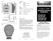
CPC05-03
CPC10-03
CPCD05-03
CPCD10-03
Installation &
Application Manual
INTRODUCTION
Thank you for purchasing the Rockford Fosgate
Connecting Punch Reinforcement Capacitor.
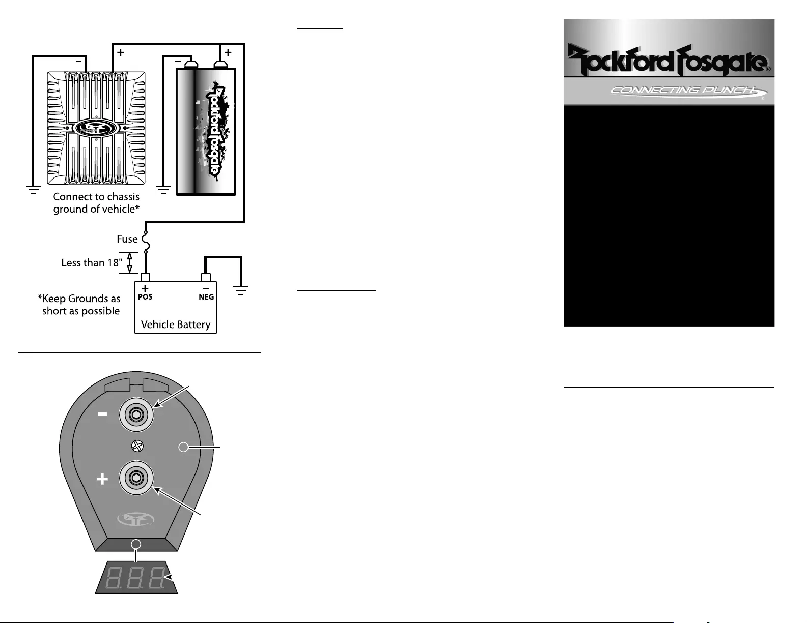
The Connecting Punch Reinforcement Capacitors
allow you to help maintain continuous power to
other devices, such as amplifiers, in your audio
system.
Please read, understand and follow all instructions
before connecting the Connecting Punch
Reinforcement Capacitor. If, after reading your
manual, you still have questions regarding this
product, we recommend that you see your
Rockford Fosgate dealer. If you need further
assistance, you can call us direct at
1-800-669-9899.
.5 Farad or 1 Farad
Reinforcement
Capacitor
01/03 Printed in U.S.A. RFMANTF-03
SPECIFICATIONS
WARRANTY INFORMATION
Rating: .5 farad
(CPC05-03, CPCD05-03)
1 farad
(CPC10-03, CPCD10-03)
VDC: 20V surge
Tolerance: -10% + 50%
Dimensions: .5 farad : 3" x 6.5" (76.2mm x 165.1mm)
1 farad : 3" x 8.625" (76.2mm x 219mm)
Digital Status Caps add 5/8" (16mm) to height
ESR: <0.00198Ω @ 120Hz 25°C
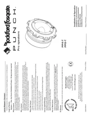
Terminals: 1/4" 28 thread
Tools: 3/16" Allen wrench
Connecting Punch
Rockford Corporation
546 South Rockford Drive
Tempe, AZ 85281 USA
USA, (480) 967-3565
Europe, Fax (49) 4207-8101250
Japan, Fax (81) 559-79-1265
Capacitors are nearly indestructible and will provide
years of service if installed and used in accordance
with the instructions in this manual. If this product
should prove to be defective within a period of
ninety (90) days from the date of purchased, contact
your dealer or Rockford Corporation Customer
Service Department at 1-800-669-9899 for
replacement instructions.
In the event the vent is blown or leaking as a result
of switched polarity, the capacitor is not covered by
warranty.
Stripped screws or terminals are not covered by
warranty. Replacements may be obtained at a
resonable cost by contacting Rockford Corporation
Customer Service Department at 1-800-669-9899
1
4
3
2
Fig. 1
Fig. 2
Produkspesifikasjoner
| Merke: | Rockford Fosgate |
| Kategori: | Ikke kategorisert |
| Modell: | Connecting Punch CPC05-03 |
Trenger du hjelp?
Hvis du trenger hjelp med Rockford Fosgate Connecting Punch CPC05-03 still et spørsmål nedenfor, og andre brukere vil svare deg
Ikke kategorisert Rockford Fosgate Manualer

19 Oktober 2025
18 Oktober 2025

18 Oktober 2025

18 Oktober 2025
18 Oktober 2025
18 Oktober 2025
18 Oktober 2025

18 Oktober 2025
18 Oktober 2025
18 Oktober 2025
Ikke kategorisert Manualer
- RCBS
- Emga
- 4ms
- Arturia
- CGV
- Eschenbach
- Artsound
- Akai
- Govee
- Scarlett
- Gardenline
- IOIO
- Eero
- Proficare
- RGBlink
Nyeste Ikke kategorisert Manualer

23 Oktober 2025

23 Oktober 2025

23 Oktober 2025

23 Oktober 2025

23 Oktober 2025

23 Oktober 2025

23 Oktober 2025

23 Oktober 2025

23 Oktober 2025

23 Oktober 2025