Tripp Lite SmartRack SRWO8U22MD Bruksanvisning
Tripp Lite
Server
SmartRack SRWO8U22MD
Les nedenfor 📖 manual på norsk for Tripp Lite SmartRack SRWO8U22MD (20 sider) i kategorien Server. Denne guiden var nyttig for 9 personer og ble vurdert med 4.2 stjerner i gjennomsnitt av 5 brukere
Side 1/20
1
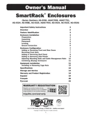
Owner’s Manual
8U/12U/22U Configurable
Wall-Mounted 2-Post Open Frame Rack
Model: SRWO8U22
1111 W. 35th Street, Chicago, IL 60609 USA • www.tripplite.com/support
Copyright © 2017 Tripp Lite. All rights reserved.
Introduction 2
Important Safety Instructions 2
Parts List 2
Installation/Wall-Mounting 3
8U Configuration 3
12U Configuration 4
22U Configuration 5
Equipment Installation 6
Storage & Service 6
Warranty & Product Registration 6
Español 7
Français 13
PROTECT YOUR INVESTMENT!
Register your product for quicker service and ultimate peace of mind.
You could also win an ISOBAR6ULTRA surge protector—a $100 value!
www.tripplite.com/warranty
17-11-213-933342.indb 1 11/29/2017 11:02:11 AM
Produkspesifikasjoner
| Merke: | Tripp Lite |
| Kategori: | Server |
| Modell: | SmartRack SRWO8U22MD |
Trenger du hjelp?
Hvis du trenger hjelp med Tripp Lite SmartRack SRWO8U22MD still et spørsmål nedenfor, og andre brukere vil svare deg
Server Tripp Lite Manualer
18 August 2025
18 August 2025

18 August 2025
18 August 2025

18 August 2025
18 August 2025
18 August 2025

18 August 2025
18 August 2025

18 August 2025
Server Manualer
- Mobotix
- Emerson
- Viewsonic
- SilverStone
- Western Digital
- Intellinet
- Acti
- Asus
- Belkin
- Smart-AVI
- Ibm
- Blackmagic Design
- Origin Storage
- Elecom
- Akasa
Nyeste Server Manualer

6 Oktober 2025
Western Digital My Cloud Mirror WDBZVM0120JWT Bruksanvisning
6 Oktober 2025
6 Oktober 2025
6 Oktober 2025
6 Oktober 2025
6 Oktober 2025
6 Oktober 2025
6 Oktober 2025
6 Oktober 2025

6 Oktober 2025