First Alert 7010B Bruksanvisning
First Alert
Røykvarsler
7010B
Les nedenfor 📖 manual på norsk for First Alert 7010B (7 sider) i kategorien Røykvarsler. Denne guiden var nyttig for 21 personer og ble vurdert med 4.7 stjerner i gjennomsnitt av 11 brukere
Side 1/7

U
S Patent 6,377,182
M
08-0050-004
Q 0
8/08 Printed in Mexico
I
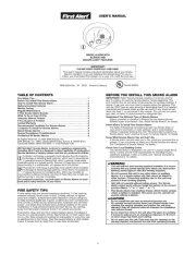
MPORTANT! PLEASE READ CAREFULLY AND SAVE.
T
his user’s manual contains important information
a
bout your Smoke Alarm’s operation. If you are
installing this Smoke Alarm for use by others, you must
l
eave this manual—or a copy of it—with the end user.
INTRODUCTION
Thank you for choosing First Alert
®
for your Smoke Alarm needs. Y
ou have
purchased a state of the art Smoke Alarm designed to provide you with an
early warning of a fire. Please take the time to read this manual and make
this Smoke Alarm an integral part of your family’
s safety plan.
Key Features of the 7010 and 7010B Smoke Alarm:
Photoelectric Smoke Sensing Technology:
Generally more sensitive at
detecting large particles, which tend to be produced in greater amounts by
smoldering fir
es.
Optipath 360 Technology
TM
: Patented technology provides 360˚ of direct
access to the smoke sensor
.
Single Button Test/Silence: One touch button combines both features.
Perfect Mount: Mounting bracket keeps alarm secure over a wide rotation
range to allow for perfect alignment.
Battery back-up (Model 7010B only): Keeps alarm functioning during a
power interruption provided battery is fresh and installed properly.
1
A
ll First Alert
®
a
nd BRK
®
S
moke Alarms conform to regulatory
requirements, including UL217 and are designed to detect particles of
c
ombustion. Smoke particles of varying number and size are produced
in all fires.
I
onization technology is generally more sensitive than photoelectric
t
echnology at detecting small particles, which tend to be produced
i
n greater amounts by flaming fires, which consume combustible
materials rapidly and spread quickly. Sources of these fires may include
paper burning in a wastebasket, or a grease fire in the kitchen.
Photoelectric technology is generally more sensitive than ionization
technology at detecting large particles, which tend to be produced in
greater amounts by smoldering fires, which may smolder for hours
before bursting into flame. Sources of these fires may include cigarettes
burning in couches or bedding.
For maximum protection, use both types of Smoke Alarms on each
level and in every bedroom of your home.
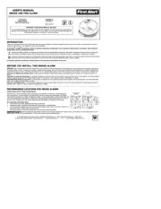
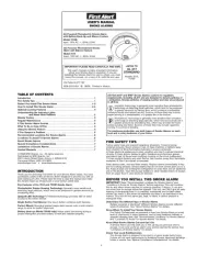
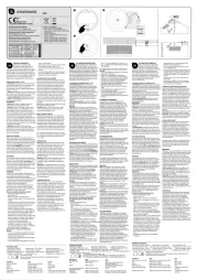
USER’S MANUAL
SMOKE ALARMS
AC Powered Photoelectric Smoke
A
larm with Silence Feature
M
odel 7010
Input: 120V AC ~, 60Hz, 0.04A
A
C Powered Photoelectric Smoke Alarm
with Battery Back-Up and Silence Feature
Model 7010B
I
nput: 120V AC
~,
60Hz, 0.04A
TABLE OF CONTENTS
Intro
duction . . . . . . . . . . . . . . . . . . . . . . . . . . . . . . . . . . . . . . . . . . . . . . . . . .1
Fire
Safety Tips
. . . . . . . . . . . . . . . . . . . . . . . . . . . . . . . . . . . . . . . . . . . . . . .1
Before
You Install This Smoke Alarm . . . . . . . . . . . . . . . . . . . . . . . . . . . .1
-2
H
ow To Install This Smoke Alarm . . . . . . . . . . . . . . . . . . . . . . . . . . . . . . .2-3
O
ptional Locking Features
. . . . . . . . . . . . . . . . . . . . . . . . . . . . . . . . . . . . . .4
Understanding the Indicator Lights
and Alarm Horn Patterns . . . . . . . . . . . . . . . . . . . . . . . . . . . . . .5
Weekly Testing . . . . . . . . . . . . . . . . . . . . . . . . . . . . . . . . . . . . . . . . . . . . . . . .5
Regular Maintenance . . . . . . . . . . . . . . . . . . . . . . . . . . . . . . . . . . . . . . . . . .5
If This Smoke Alarm Sounds . . . . . . . . . . . . . . . . . . . . . . . . . . . . . . . . . . . .5
What To Do In Case Of Fire . . . . . . . . . . . . . . . . . . . . . . . . . . . . . . . . . . . . .5
Using the Silence Feature . . . . . . . . . . . . . . . . . . . . . . . . . . . . . . . . . . . . . . .5
If You Suspect a Problem . . . . . . . . . . . . . . . . . . . . . . . . . . . . . . . . . . . . . . .6
Recommended Locations For Smoke Alarms . . . . . . . . . . . . . . . . . . . . . .6
Locations To Avoid For Smoke Alarms . . . . . . . . . . . . . . . . . . . . . . . . . . . .6
About Smoke Alarms . . . . . . . . . . . . . . . . . . . . . . . . . . . . . . . . . . . . . . . . . .7
Special Compliance Considerations . . . . . . . . . . . . . . . . . . . . . . . . . . . . . .7
Limitations of Smoke Alarms . . . . . . . . . . . . . . . . . . . . . . . . . . . . . . . . . . . .7
Limited Warranty . . . . . . . . . . . . . . . . . . . . . . . . . . . . . . . . . . . . . . . . . . . . . .7
© 2008 BRK Brands, Inc. All rights reserved.
Distributed by BRK Brands, Inc.
3901 Liberty Street Road, Aur
ora, IL 60504-8122
Consumer Affairs: (800) 323-9005
www.firstalert.com • www.brkelectronics.com
FIRE SAFETY TIPS
Follow safety rules and prevent hazardous situations: 1) Use smoking
materials properly. Never smoke in bed. 2) Keep matches or lighters away
from children; 3) Store flammable materials in proper containers;
4) Keep electrical appliances in good condition and don’t overload electrical
circuits; 5) Keep stoves, barbecue grills, fireplaces and chimneys grease-
and debris-free; 6) Never leave anything cooking on the stove unattended;
7) Keep portable heaters and open flames, like candles, away from flammable
materials; 8) Don’t let rubbish accumulate.
Keep alarms clean, and test them weekly. Replace alarms immediately if they
are not working properly. Smoke Alarms that do not work cannot alert you to a
fire. Keep at least one working fire extinguisher on every floor, and an additional
one in the kitchen. Have fir
e escape ladders or other reliable means of escape
from an upper floor in case stairs are blocked.
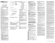
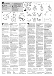
BEFORE YOU INST
ALL THIS SMOKE ALARM
IMPORTANT! Read “Recommended Locations for Smoke Alarms” and
“Locations to Avoid for Smoke Alarms” before beginning. This unit monitors
the air, and when smoke reaches its sensing chamber, it alarms. It can give
you mor
e time to escape before fire spreads. This unit can ONLY give an early
warning of developing fires if it is installed, maintained and located where
smoke can reach it, and where all residents can hear it, as described in this
manual. This unit will not sense gas, heat, or flame. It cannot prevent or
extinguish fires.
Understand The Different Type of Smoke Alarms
Battery powered or electrical? Different Smoke Alarms provide different
types of protection. See “About Smoke Alarms” for details.
Know Wher
e T
o Install Y
our Smoke Alarms
Fir
e Safety
Professionals recommend at least one Smoke Alarm on every
level of your home, in every bedroom, and in every bedroom hallway or
separate sleeping area. See “Recommended Locations For Smoke Alarms”
and “Locations T
o A
void For Smoke Alarms” for details.
Know What Smoke Alarms Can and Can’t Do
A Smoke Alarm can help alert you to fir
e, giving you pr
ecious time to
escape. It can only sound an alarm once smoke reaches the sensor. See
“Limitations of Smoke Alarms” for details.
Check Your Local Building Codes
This Smoke Alarm is designed to be used in a typical single-family home.
It alone will not meet requirements for boarding houses, apartment buildings,
hotels or motels. See “Special Compliance Considerations”
for details.
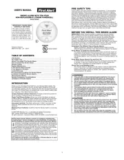
Models 7010,
7
010B
L
ISTED TO
UL 217
STANDARD
Produkspesifikasjoner
| Merke: | First Alert |
| Kategori: | Røykvarsler |
| Modell: | 7010B |
Trenger du hjelp?
Hvis du trenger hjelp med First Alert 7010B still et spørsmål nedenfor, og andre brukere vil svare deg
Røykvarsler First Alert Manualer

15 September 2025
15 September 2025
15 September 2025
15 September 2025
15 September 2025
15 September 2025

15 September 2025
15 September 2025

15 September 2025
15 September 2025
Røykvarsler Manualer
- X-Sense
- Hochiki
- Kogan
- Gloria
- Elgato
- Logilink
- Nedis
- Ferguson
- EQ-3
- Somfy
- Pentatech
- Smartwares
- SAVS
- ESYLUX
- Qolsys
Nyeste Røykvarsler Manualer

30 September 2025
15 September 2025

15 September 2025
15 September 2025
15 September 2025
15 September 2025
11 September 2025
11 September 2025
11 September 2025
8 September 2025