Biltema 25-5099 Bruksanvisning
Les nedenfor 📖 manual på norsk for Biltema 25-5099 (20 sider) i kategorien solcelle. Denne guiden var nyttig for 12 personer og ble vurdert med 5.0 stjerner i gjennomsnitt av 6.5 brukere
Side 1/20
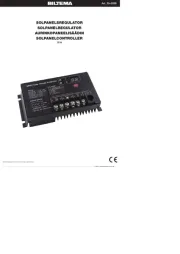
Art. 25-5099
© 2022-11-09 Biltema Nordic Services AB
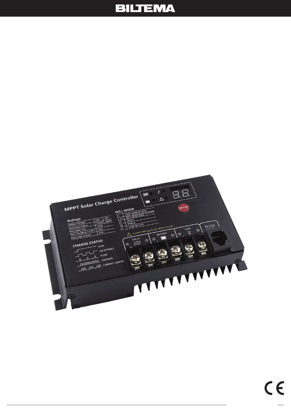
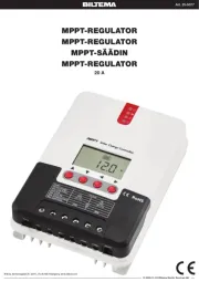
SOLPANELSREGULATOR
SOLPANELREGULATOR
AURINKOPANEELISÄÄDIN
SOLPANELCONTROLLER
10 A
25-5099_Manual A4_221103.indd • 2022-11-9, 15.58.40
Biltema, Garnisonsgatan 26, 2nd FL, SE-254 66 Helsingborg. www.biltema.com
Produkspesifikasjoner
| Merke: | Biltema |
| Kategori: | solcelle |
| Modell: | 25-5099 |
Trenger du hjelp?
Hvis du trenger hjelp med Biltema 25-5099 still et spørsmål nedenfor, og andre brukere vil svare deg
solcelle Biltema Manualer
12 September 2025
11 September 2025
11 September 2025
10 September 2025
10 September 2025
10 September 2025
solcelle Manualer
- Deye
- SereneLife
- EcoFlow
- AEG
- MSW
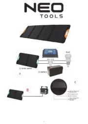
- NEO Tools
- Osram
- Ryobi
- Reolink
- Growatt
- Technaxx
- Jackery
- Mestic
- Salicru
- Xtorm
Nyeste solcelle Manualer
20 Oktober 2025
12 Oktober 2025
12 Oktober 2025
7 Oktober 2025
7 Oktober 2025
7 Oktober 2025
29 September 2025
15 September 2025
8 September 2025

7 September 2025