Valcom ezIP EZ-DIBR Bruksanvisning

Valcom Ikke kategorisert ezIP EZ-DIBR

Les nedenfor 📖 manual på norsk for Valcom ezIP EZ-DIBR (5 sider) i kategorien Ikke kategorisert. Denne guiden var nyttig for 2 personer og ble vurdert med 4.9 stjerner i gjennomsnitt av 1.5 brukere

Side 1/5
1 9471000
ISSUE 1
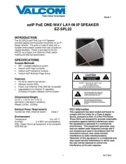
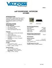
ezIP DOORPHONE / INTERCOM
EZ-DIBR
INTRODUCTION
The EZ-DIBR IP Talkback DoorPhone / Intercom
allows communication to Valcom ezIP Page
Controllers, ezIP Interactive Consoles and SIP
based telephone systems via an IP-based
network.
SPECIFICATIONS
Access Methods
SIP enabled telephone system
ezIP Page Controller
ezIP Interactive Console
Valcom ezIP Multicast Page Group
Features
Vandal-resistant stainless steel faceplate
1 Form C relay
Network activity LEDs
Power over Ethernet (PoE) 802.3af
compatible
Upgradable to full Valcom VIP speaker
functionality
Dimensions/Weight:
EZ-DIBR
4.5” H x 4.5" W x 1.75" D
(11.43cm H x 11.43cm W x 4.45cm D)
Weight: 1.68 lbs. (0.76 kg)
Network Interface
1.62” H x 5.63” W x 3.45” D
(4.11 cm) x (14.30 cm) x (8.73 cm)
with brackets 8.22” W (20.87 cm)
Weight: 2.10 lbs. (0.95 kg)
EZ-DIBR Network Interface
Nominal Specifications
Input Impedance: 600 Ohms
Input Level: -10dBm
Output Impedance: 600 Ohms
Output Level: -10dBm nominal
Relay Current: 1 AMP @ 24VDC
Nominal Power Requirements
Via 802.3af PoE Ethernet Switch: Class 3
Environment
Network Interface:
Temperature: 0 to +40° C
Humidity: 0 to 85% non-precipitating
Indoor installation only
EZ-DIBR Speaker Door plate:
Suitable for indoor or outdoor installation
2 9471000
CAUTION: To reduce the risk of electric shock,
Do not remove cover.
No user serviceable parts inside.
Refer servicing to qualified service personnel.
CAUTION
RISK OF ELECTRIC SHOCK
DO NOT OPEN
This symbol indicates that dangerous
voltage constituting a risk of electric
shock is present within this unit.
This symbol indicates that there are
important operating and maintenance
instructions in the literature accompanying
this unit.
Precautionary Designations
FCC Information
This equipment has been tested and found to
comply with the limits for a Class A digital
device, pursuant to Part 15 of the FCC Rules.
These limits are designed to provide
reasonable protection against harmful
interference when the equipment is operated
in a commercial environment. This
equipment generates uses and can radiate
radio frequency energy and if not installed
and used in accordance with the instruction
manual, may cause harmful interference to
radio communications. Operation of this
equipment in a residential area may cause
harmful interference in which case the user
will be required to correct the interference at
his own expense.
INSTALLATION
Operation:
The EZ-DIBR provides door intercom access via
network connection to customer telephone
system, Valcom ezIP Page Controller or Valcom
ezIP Interactive Console. Interface to customer
telephone system can be via SIP registration to a
voice over IP (VoIP) telephone system, or FXO or
FXS port (when used with an ezIP Page
Controller). Pressing the call button on the door
plate initiates a call to a user-specified telephone
number and the call assurance LED on the door
plate begins to flash. When the call is answered,
a hands-free communications path is established
to the door plate, and the call assurance LED on
the door plate remains lit. The form C relay
included with the EZ-DIBR may be activated by
pressing the # key on the answering telephone,
with the relay typically being used to activate door
entry equipment.
Mounting
For enhanced protection against static
electrical discharge, it is recommended the
speaker faceplate shipped with the EZ-DIBR
be installed into a grounded electrical box.
The EZ-DIBR DoorPhone is designed for double
gang FD electrical box mounting and must be
within 900 feet of the Network Interface. See
NEMA OS 3-2002 sec.1.2.3.5 for FD box
specifications.
The Network Interface is designed for wall
mounting and must be within 100 meters of the
network switch. Using the wood screws and
mounting brackets provided, secure the Network
Interface to the wall.
Power Connections
The only method of powering the Network
Interface is via a Power over Ethernet (PoE)
switch or power injector meeting the 802.3af
specification.
Make all required signal connections before
connecting to Ethernet switch or power injector
meeting the 802.3af specification.
Network Connection
The Network Interface has one RJ-45 Network
connector and one RJ-45 Signal Output
connector on the front panel.
Use a standard Ethernet patch cable to connect
the NETWORK connector of the Network
Interface to an Ethernet switch.
Signal Connections
Connect RJ-45 using EIA/TIA 568B Standard to
the signal connector of the Network Interface
then to the RJ-45 connector of the EZ-DIBR
DoorPhone.
Door Relay Connections
Access to the form C relay is provided via a
three-pin screw terminal block on the EZ-DIBR
DoorPhone speaker assembly. The common
contact is the middle terminal. The normally
open contact is on the side closest to the RJ-45
connector, the normally closed contact is on the
side furthest from the RJ-45 connector. For
higher security, the included VIP172-RLY
connection block can be used. Please refer to
Figure 2 for wiring connections.

Produkspesifikasjoner

Merke: Valcom
Kategori: Ikke kategorisert
Modell: ezIP EZ-DIBR

Trenger du hjelp?

Hvis du trenger hjelp med Valcom ezIP EZ-DIBR still et spørsmål nedenfor, og andre brukere vil svare deg