Valcom V-9925A Bruksanvisning
Valcom
Ikke kategorisert
V-9925A
Les nedenfor 📖 manual på norsk for Valcom V-9925A (3 sider) i kategorien Ikke kategorisert. Denne guiden var nyttig for 16 personer og ble vurdert med 3.5 stjerner i gjennomsnitt av 8.5 brukere
Side 1/3

Issue 8
1 947925A
V-9925A
LOUD WARBLE RINGER WITH VOLUME CONTROL
5 WATT -24VDC
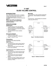
INTRODUCTION
These instructions contain the specifications and
guidelines necessary to install, operate and maintain
the V-9925A, 5-Watt Loud Warble Ringer with
Volume Control.
SPECIFICATIONS
The V-9925A Loud Warble Ringer is a
self-contained 5-Watt electronic ringer which can be
used for either interior or exterior signaling
applications. The unit is designed to allow a loud
warble to be broadcast as long as input signal is
present. The input signal should be interrupted or
controlled by the ringing interval.
Application
Loud speaker tone signaling for key systems,
intercoms, PABXs
Outside signaling for incoming calls into a key
system
Signaling in a noisy environment
Features
5 Watt amplifier
Volume control
High efficiency horn
Tone generation circuitry
Coverage
Refer to the following table for speaker coverage.
The first number given is the side to side distance for
mounting the speakers. It is also the distance in front
of the speaker that you can expect to hear a good
quality signal. The second number is the area being
covered in square feet.
Location Distance Area
Quiet 220 ft. 48,400 sq. ft.
Moderate 160 ft. 25,600 sq. ft.
Noisy 80 ft. 6,400 sq. ft.
Very Noisy 40 ft. 1,600 sq. ft.
Environmental
Temperature: -20 to +55°C
Humidity: 0 to 95% (non-precipitating)
Dimensions/Weight
6.50"H x 8.20"W x 10.40"D,
plus mounting base
(16.51cm H x 20.83cm W x 26.42cm D)
3.6 lbs. (1.63kg)
Signal/Power Requirements
Power Supply: -24VDC, 500mA ("B" Battery)
(10 Valcom power units)
Signal Source: 105VAC or 20VAC
Produkspesifikasjoner
| Merke: | Valcom |
| Kategori: | Ikke kategorisert |
| Modell: | V-9925A |
| Bredde: | 208.2 mm |
| Dybde: | 264 mm |
| Høyde: | 165.1 mm |
| Tilkoblingsteknologi: | Koblet med ledninger (ikke trådløs) |
| Anbefalt bruk: | Andre |
| Høyttalerplassering: | Tak-Monterbart |
| Forsterker: | Innebygget |
| Produktfarge: | Beige |
| AC-adapter utgangsspenning: | 24 V |
| Strøminngang/AC (strøm) inn: | Ja |
| Strøm: | 0.5 A |
| Lyd-utgang kanaler: | 1.0 kanaler |
| RMS-rangert strøm/utgangseffekt: | 5 W |
| Utjevner/frekvenskorrigerer: | Nei |
| Antall drivere: | 1 |
| Høyttaler type: | 1-veis |
| Frekvensrekkevidde: | - Hz |
Trenger du hjelp?
Hvis du trenger hjelp med Valcom V-9925A still et spørsmål nedenfor, og andre brukere vil svare deg
Ikke kategorisert Valcom Manualer
10 Oktober 2025
9 Oktober 2025
9 Oktober 2025
9 Oktober 2025
8 Oktober 2025
8 Oktober 2025
8 Oktober 2025
8 Oktober 2025

8 Oktober 2025
18 September 2025
Ikke kategorisert Manualer
- Krone
- BeSafe
- Gys
- Newline
- ZLine
- Shure
- JBL
- Livall
- 4ms
- Sebo
- Nordic Winter
- Exquisit
- Playseat
- Pliant Technologies
- Fein
Nyeste Ikke kategorisert Manualer

23 Oktober 2025

23 Oktober 2025

23 Oktober 2025

23 Oktober 2025

23 Oktober 2025

23 Oktober 2025

23 Oktober 2025

23 Oktober 2025

23 Oktober 2025

23 Oktober 2025