Valcom VIP-176A-IC Bruksanvisning
Valcom
Ikke kategorisert
VIP-176A-IC
Les nedenfor 📖 manual på norsk for Valcom VIP-176A-IC (4 sider) i kategorien Ikke kategorisert. Denne guiden var nyttig for 19 personer og ble vurdert med 4.7 stjerner i gjennomsnitt av 10 brukere
Side 1/4

1 947572
CAUTION: To reduce the risk of electric shock,
Do not remove cover.
No user serviceable parts inside.
Refer servicing to qualified service personnel.
CAUTION
RISK OF ELECTRIC SHOCK
DO NOT OPEN
This symbol indicates that dangerous
voltage constituting a risk of electric
shock is present within this unit.
This symbol indicates that there are
important operating and maintenance
instructions in the literature accompanying
this unit.
ISSUE 1
VIP-176A-IC
InformaCast
®
Compliant
SIP Door Intercom
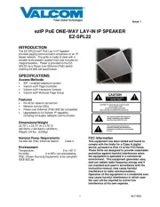
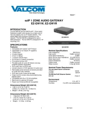
INTRODUCTION
The VIP-176A-IC InformaCast Compliant SIP
Talkback Door Intercom allows communication to
SIP-based telephone systems or Valcom
Enhanced Station Port adapters via an IP-based
network.
SPECIFICATIONS
Access Methods
InformaCast Server
SIP – enabled telephone system
PBX, FXO Port w/Valcom Enhanced Station
Port
POTS telephone set w/Valcom Enhanced
Station Port
Valcom M Cast Page Group
Features
RJ-45 for network connection
1 Form C Smart Relay (optional)
Network activity LEDs
Power over Ethernet (PoE) 802.3af
compatible
Dimensions/Weight:
4.88” H x 4.88" W x 2.5" D (including button)
(12.4cm H x 12.4cm W x 6.4cm D)
Weight: 0.82 lbs. (0.37 kg)
Nominal Power Requirements
Via 802.3af PoE Ethernet Switch: Class 3
Environment
Network Interface:
Temperature: 0 to +40° C
Humidity: 0 to 85% non-precipitating
Suitable for indoor or outdoor installation,
protected from direct precipitation.
Precautionary Designations
FCC Information
This equipment has been tested and found to
comply with the limits for a Class A digital
device, pursuant to Part 15 of the FCC Rules.
These limits are designed to provide
reasonable protection against harmful
interference when the equipment is operated
in a commercial environment. This
equipment generates uses and can radiate
radio frequency energy and if not installed
and used in accordance with the instruction
manual, may cause harmful interference to
radio communications. Operation of this
equipment in a residential area may cause
harmful interference in which case the user
will be required to correct the interference at
his own expense.
Produkspesifikasjoner
| Merke: | Valcom |
| Kategori: | Ikke kategorisert |
| Modell: | VIP-176A-IC |
Trenger du hjelp?
Hvis du trenger hjelp med Valcom VIP-176A-IC still et spørsmål nedenfor, og andre brukere vil svare deg
Ikke kategorisert Valcom Manualer
10 Oktober 2025
9 Oktober 2025
9 Oktober 2025
9 Oktober 2025
8 Oktober 2025
8 Oktober 2025
8 Oktober 2025
8 Oktober 2025

8 Oktober 2025
18 September 2025
Ikke kategorisert Manualer
- Vacmaster
- BZBGear
- Smartwares
- Cartrend
- Wasp
- Govee
- Sabrent
- Jet-Tech
- Xuma
- Eldom
- Storcube
- Hitachi
- Florabest
- Cosi Home
- MEPROLIGHT
Nyeste Ikke kategorisert Manualer

23 Oktober 2025

23 Oktober 2025

23 Oktober 2025

23 Oktober 2025

23 Oktober 2025

23 Oktober 2025

23 Oktober 2025

23 Oktober 2025

23 Oktober 2025

23 Oktober 2025